- Overview
- Creating a new DC VPN 20 Feature Template
- Creating the Policy
- Configuring Network Constructs
- Adding a Custom Control Policy
- Activity Verification
Overview
Cisco SD-WAN builds out a full mesh network between sites by default for all VPNs. This might not be desirable in some cases, where there is a requirement of a Hub and Spoke or a partial mesh topology.
Cisco SD-WAN Policies allow us to enforce a custom topology, thereby controlling the data flow within our network. We will be setting up a Hub and Spoke topology for VPN 20 at all Branch sites, steering data to the DC site, post which it will be routed to its destination. Other VPNs in the network will retain full mesh connectivity. First, let’s check the current status of the connectivity.
-
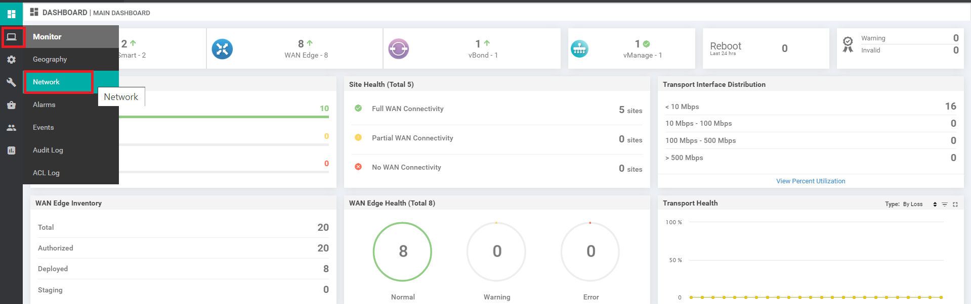
Log in to the vManage GUI and navigate to Monitor => Network
-
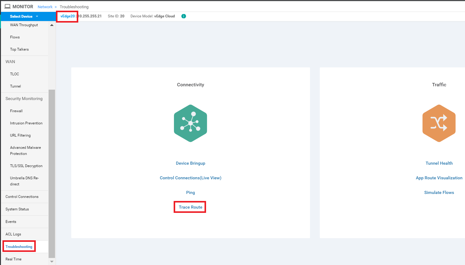
Click on vEdge20 and scroll down to Troubleshooting. Click on it and then choose Trace Route
-
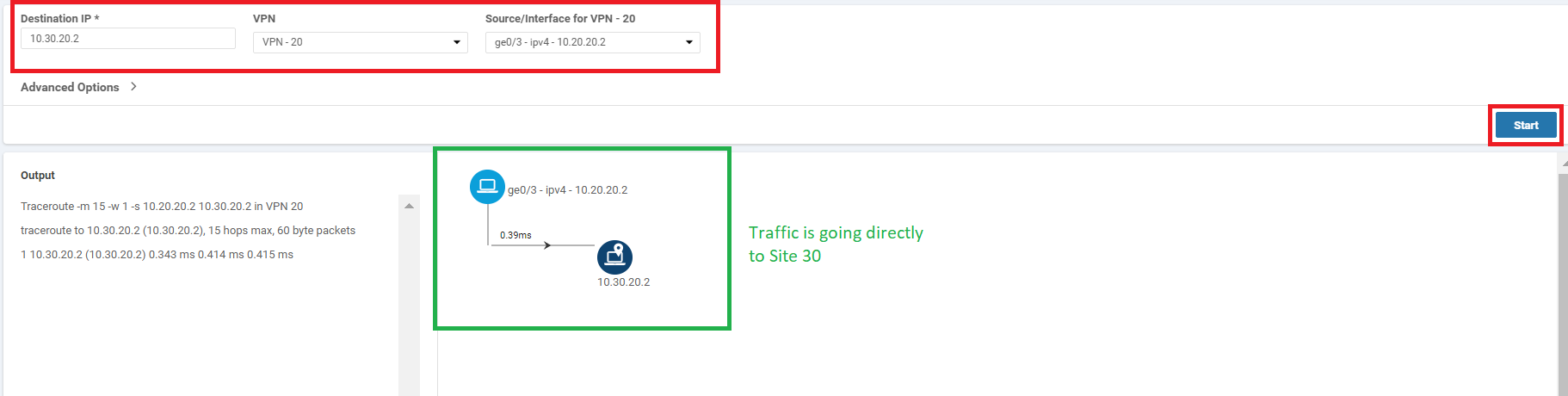
Enter the Destination IP as 10.30.20.2, choose VPN as VPN - 20 and populate the Source/Interface as ge0/3. Click on Start. You will notice that traffic is flowing directly between the two sites (i.e. Site 20 and Site 30) in VPN 20 (if there are multiple hops shown in the image in your POD, run the test again)
-
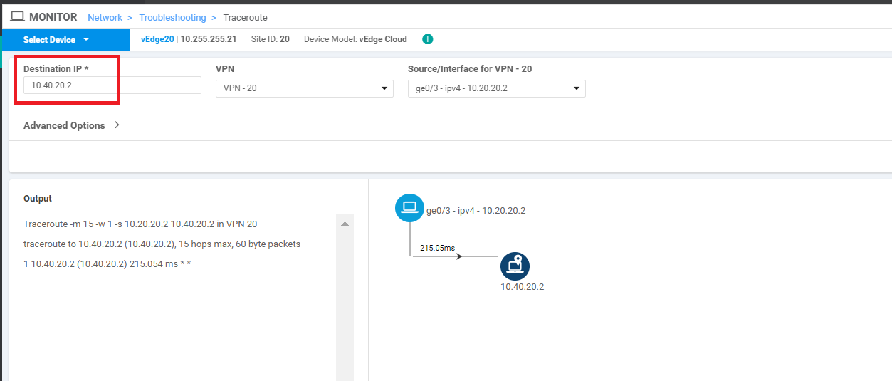
Run another test, this time to the Destination IP of 10.40.20.2. Traffic again flows directly between the sites
-
Log in to the CLI of cEdge40 via Putty and issue a
show ip route vrf 20. We will see that routes point directly to the sites, thereby facilitating full mesh connectivity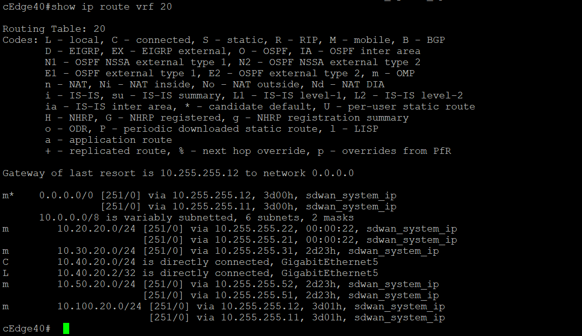
show ip route vrf 20 -
Log in to the CLI of vEdge20 and issue a
show ip route vpn 20. Once again, routes are pointing directly to the corresponding site, which is expected behaviour (you will see routes on the mpls color as well). We will be looking at changing this in the upcoming sections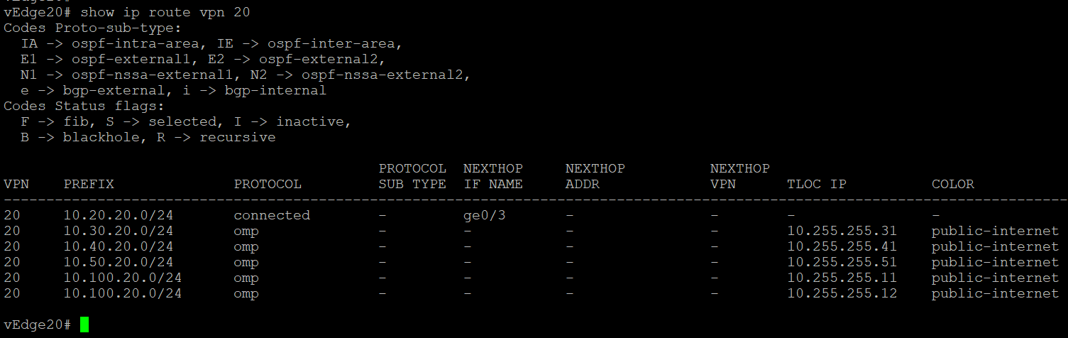
-
- Creating a new DC VPN 20 Feature Template
- Creating the Policy
- Configuring Network Constructs
- Adding a Custom Control Policy
- Activity Verification
Creating a new DC VPN 20 Feature Template
-
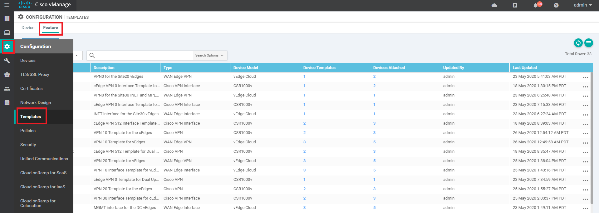
Go to Configure => Templates => Feature tab on the vManage GUI
-
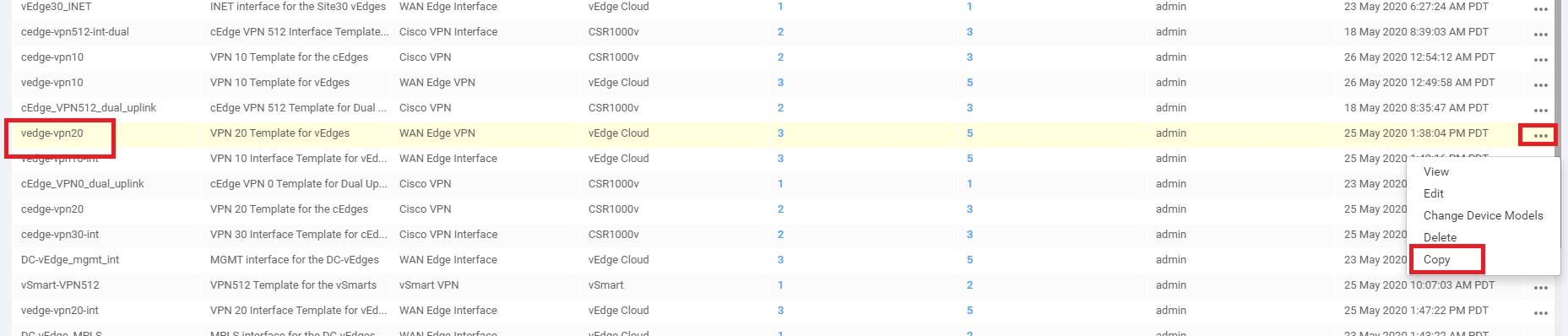
Locate the vedge-vpn20 Feature Template and click on the dots next to it. Choose to make a Copy of this template
-
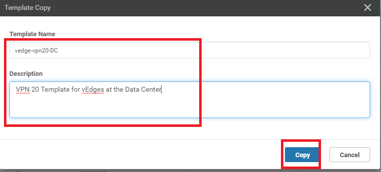
Rename the template vedge-vpn20-DC with a Description of VPN 20 Template for vEdges at the Data Center and click on Copy
-
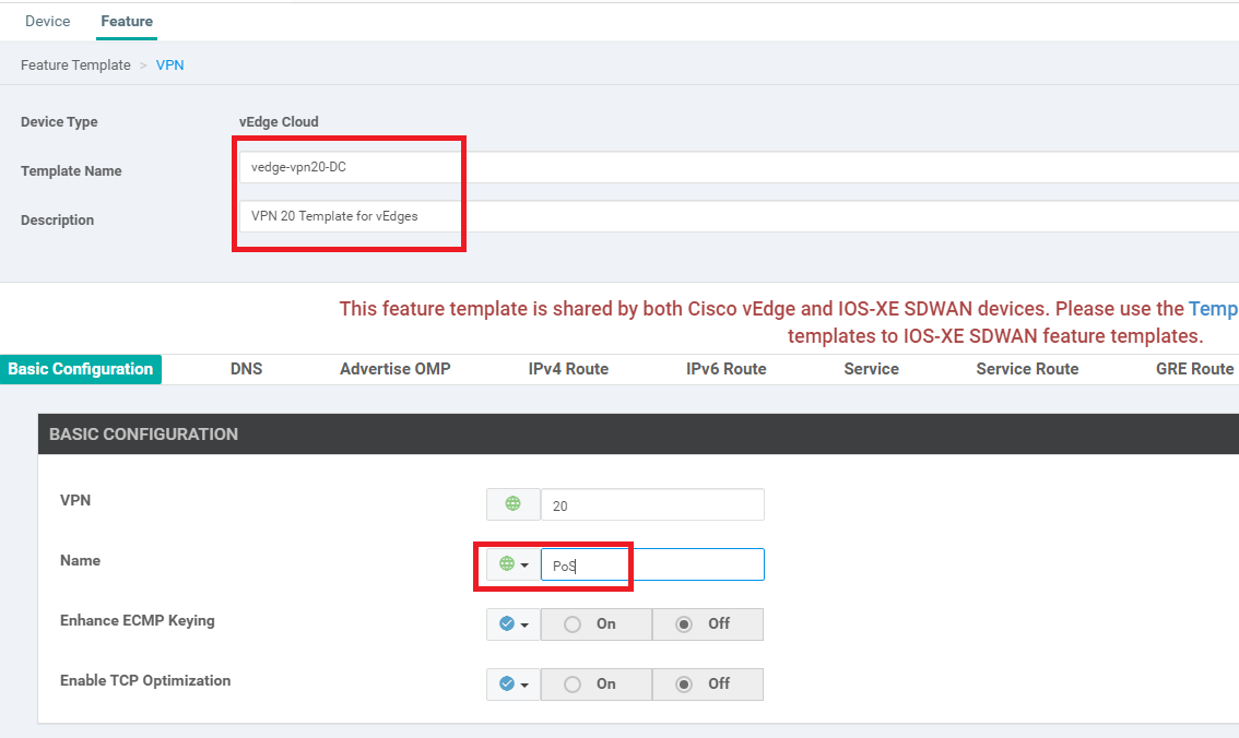
Click on the dots next to the newly created template and choose to Edit it. Make sure that the Template Name and Description match and modify the Name field under Basic Configuration to a Global value of PoS
-
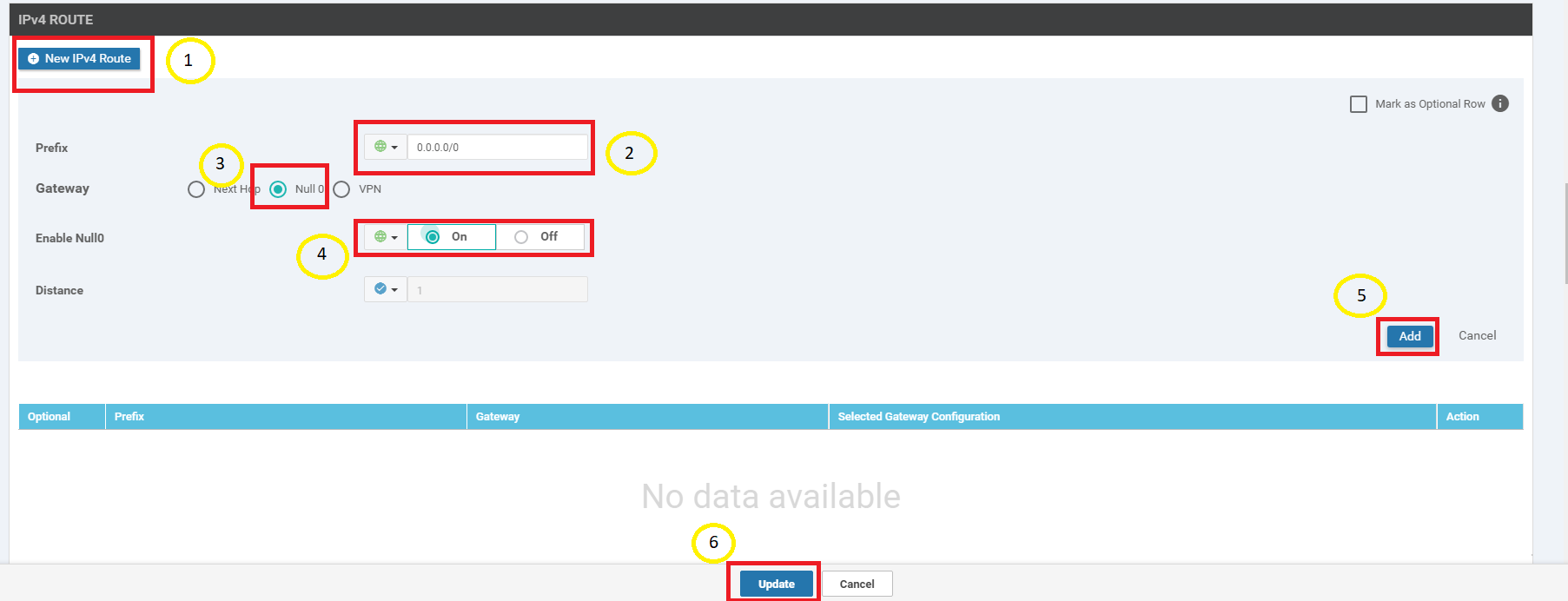
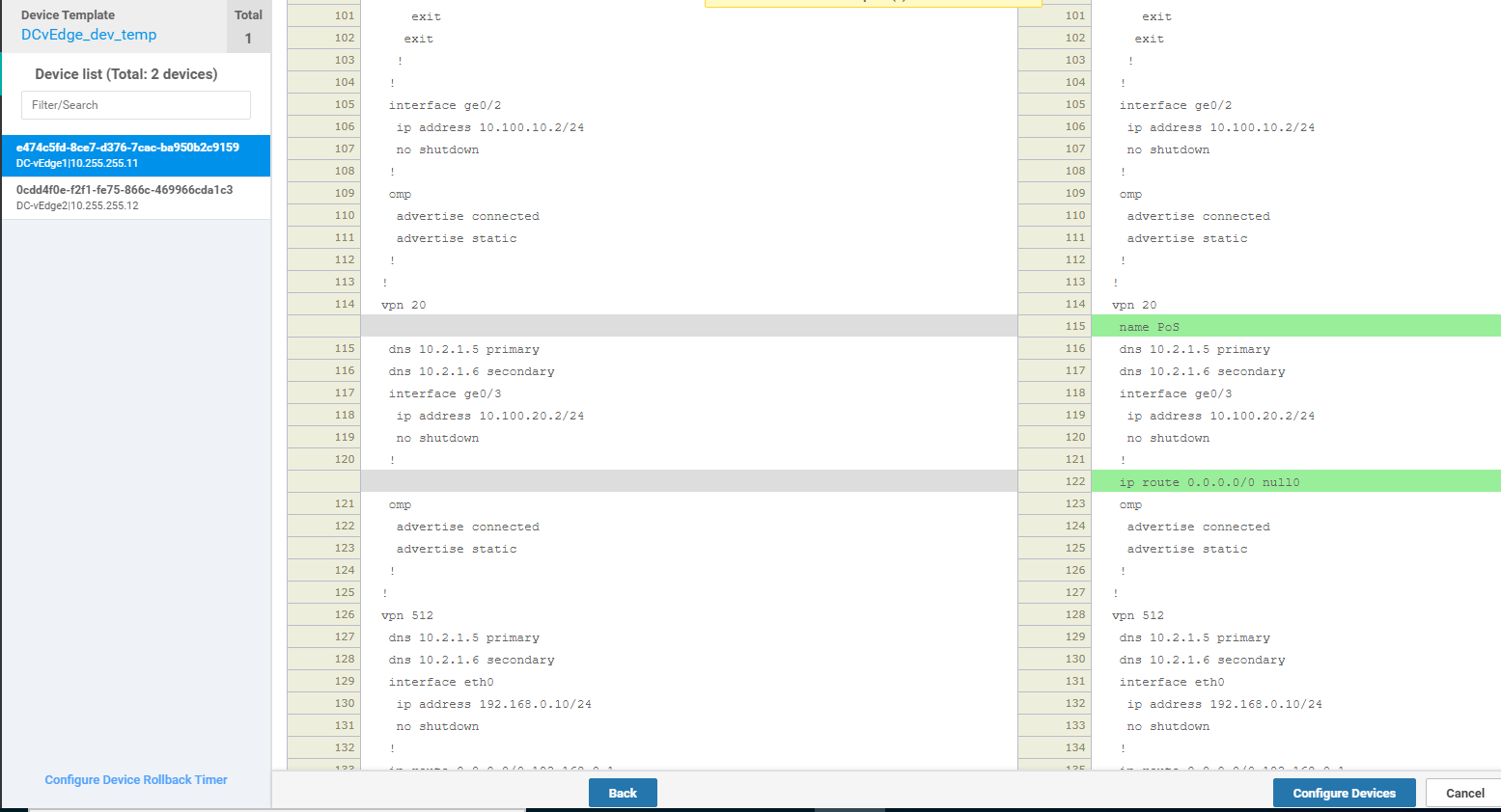
Under IPv4 Route click on New IPv4 Route. Enter a Prefix of 0.0.0.0/0 and set the Gateway as Null 0. Toggle Enable Null0 to a Global value of On and click on Add. Click on Update to update this Feature Template
-
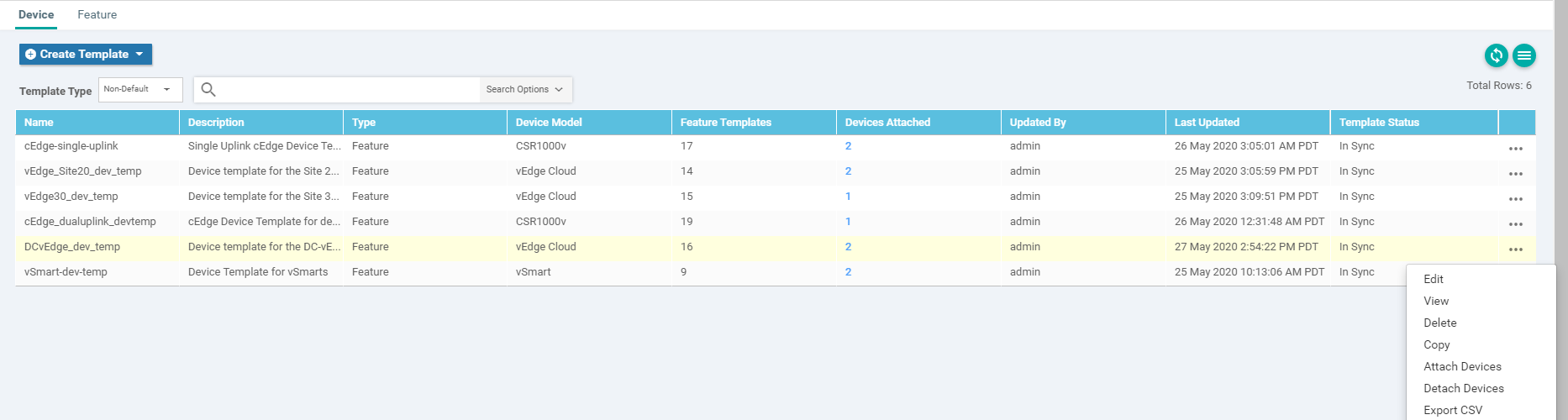
Go to Configuration => Templates => Device Tab and locate the DCvEdge_dev_temp. Click on the three dots to the template and choose to Edit
-
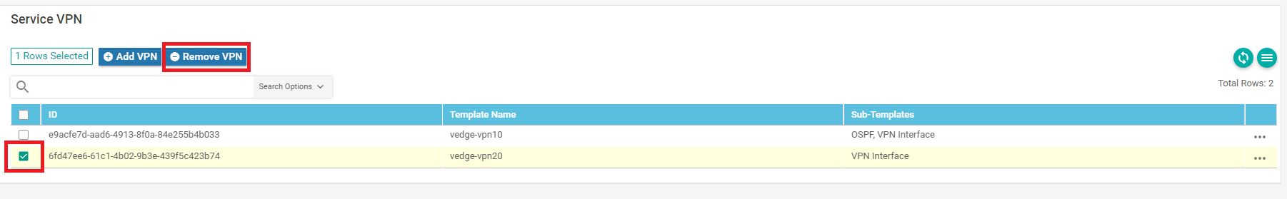
Scroll to the Service VPN section, select the vedge-vpn20 Template and choose Remove VPN (don’t worry, we will be adding it again, with the template we just created in steps 4 and 5)
-
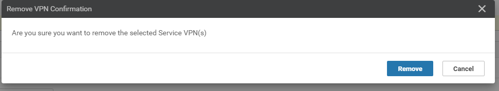
Confirm removal of the VPN by clicking on Remove
-
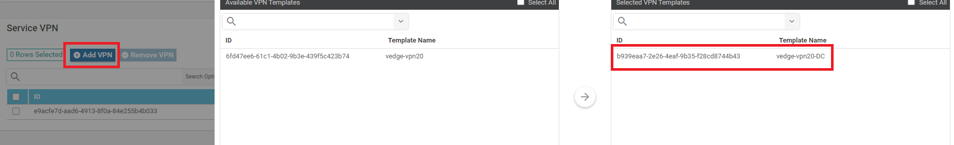
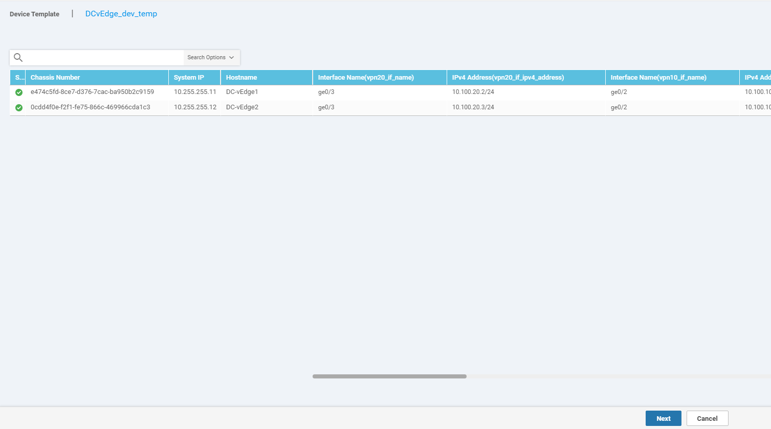
Back on the Device Template, click on Add VPN under Service VPN. Move the vedge-vpn20-DC Template to the Selected VPN Templates section and click on Next
-
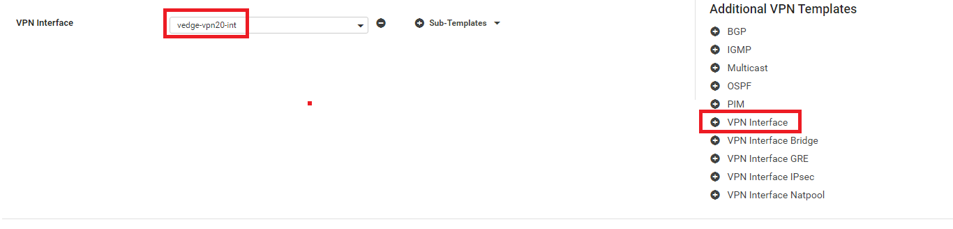
Click on VPN Interface under Additional VPN Tempaltes and populate vedge-vpn20-int in the VPN Interface drop down. Click on Add. This should take you back to the Device Template page. Click on Update
-
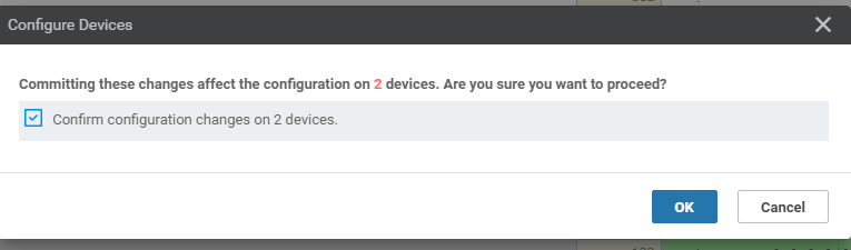
Click on Next followed by Configure Devices in the ensuing pages (you can choose to check the side-by-side configuration before choosing to Configure Devices)
-
Confirm the change on 2 devices (the DC-vEdges)
-
Once complete, go to the CLI of vEdge20 via Putty and issue
show ip route vpn 20again. You should notice default routes pointing to the DC-vEdges (at this point, site to site traffic will still not go via the DC-vEdges. For this, we will need to implement control policies)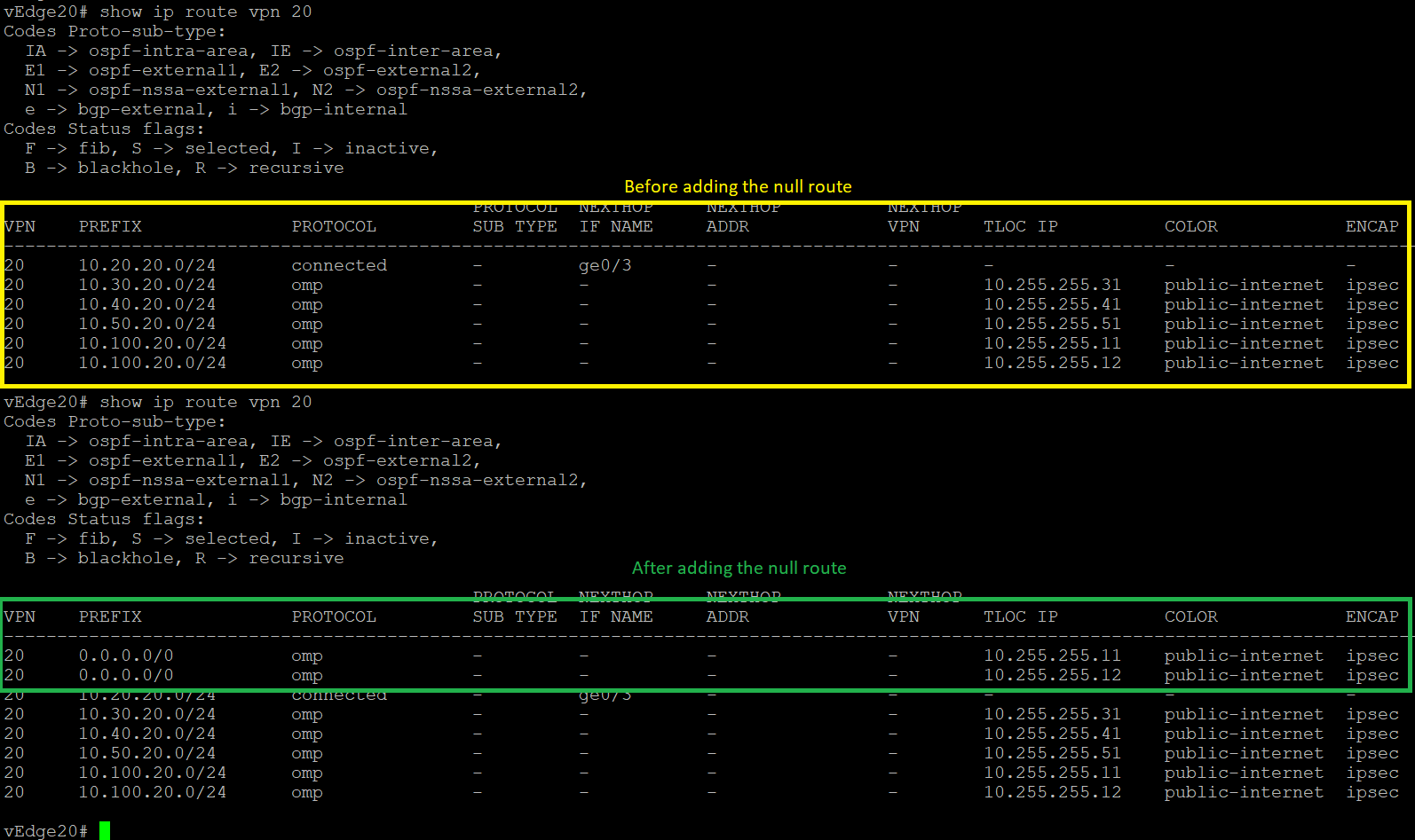
show ip route vpn 20
We have completed updating our Device Template to support a Hub and Spoke topology for VPN 20. Enforcement of the Hub and Spoke topology will be done in the following sections.
-
-
- Creating the Policy
- Configuring Network Constructs
- Adding a Custom Control Policy
- Activity Verification
Creating the Policy
We will now start enforcement of the Hub and Spoke topology via Control Policies. This is kicked off by creating a Policy which encompasses various Network Constructs (like Site Lists, VPN Lists etc.) that are used within the Policy.
Configuring Network Constructs
-
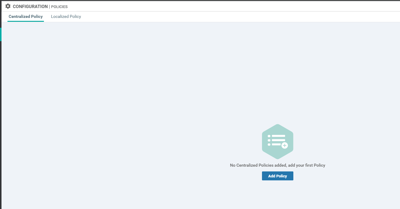
First, let’s create our overarching policy. Through this policy, we will create our Network Constructs. Click on Configuration => Policies in the vManage GUI to start configuring the Policy

-
Click on Add Policy
-
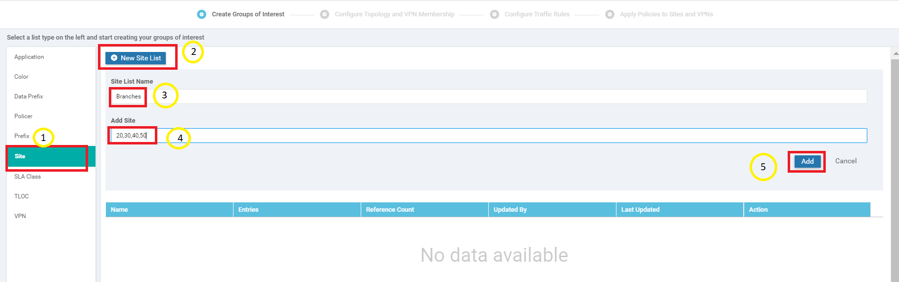
We will first create a Site List. Click on Sites and then choose New Site List. Give it a name of Branches and enter 20,30,40,50 in the Add Site section. Click on Add
-
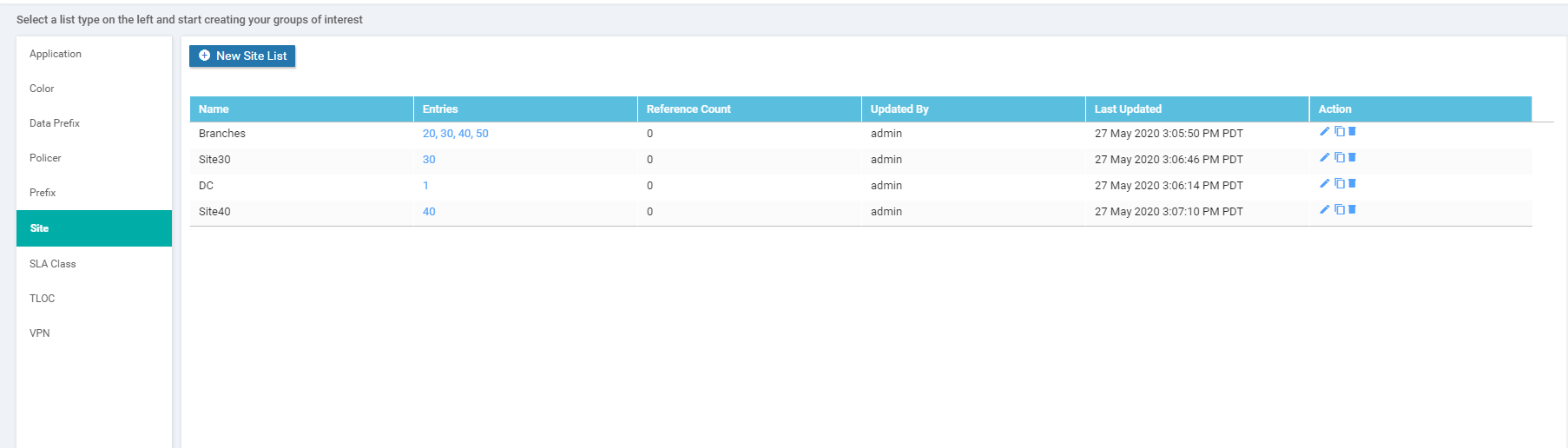
Three more Site Lists need to be created in a similar fashion. Some won’t be used right now, but it’s best to create them while we’re here. Use the table and images below as reference points
Site List Name Add Site DC 1 Site30 30 Site40 40 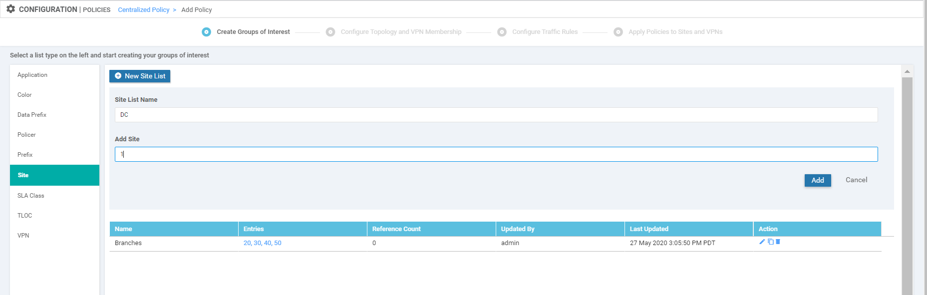
Site List for the DC 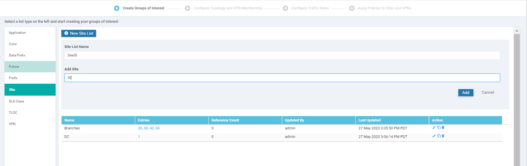
Site List for Site 30 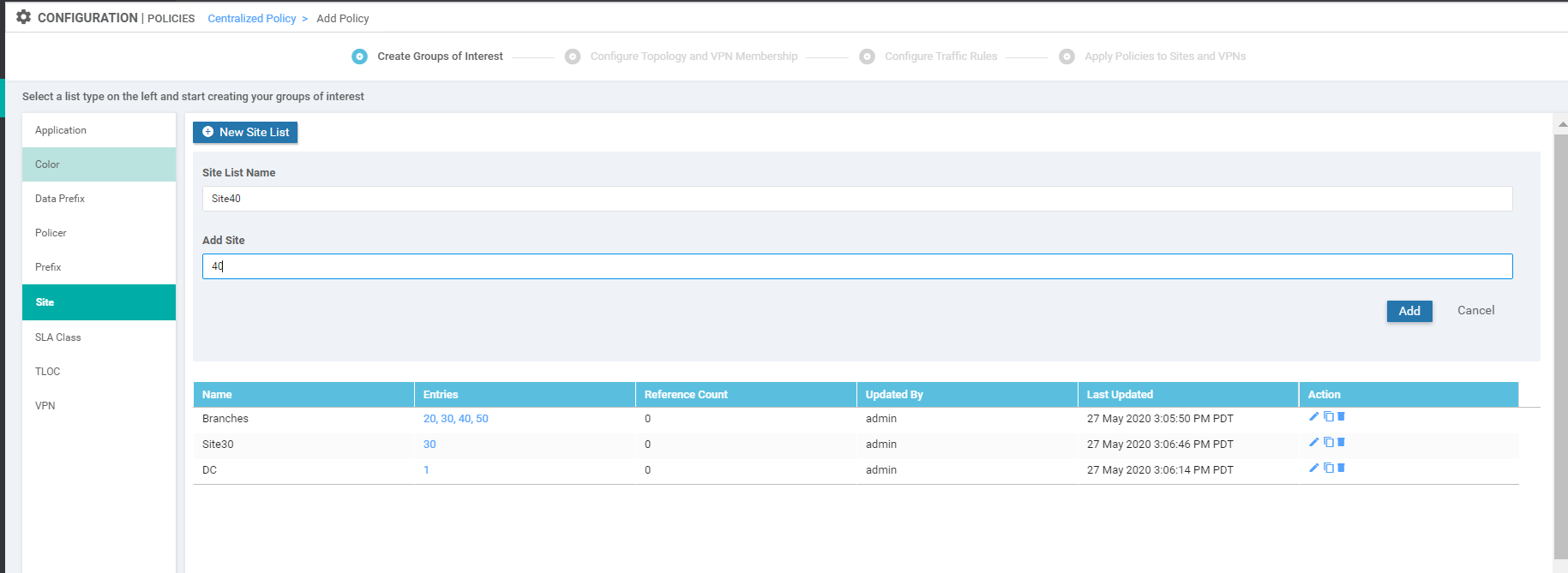
Site List for Site 40 -
Once all the Site Lists are configured, it should look like this
-
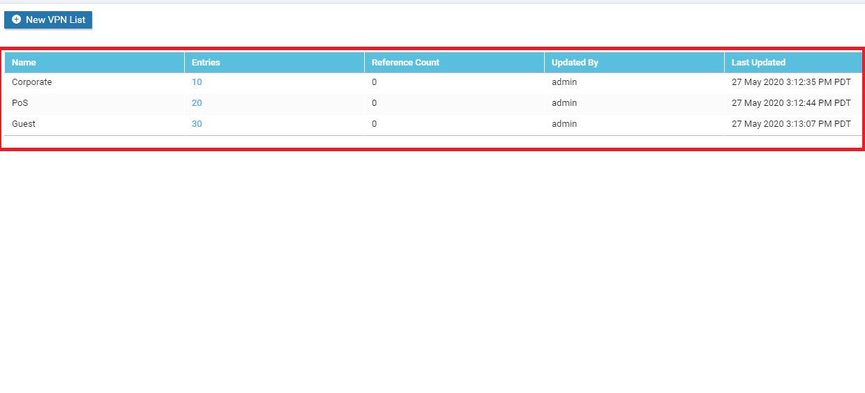
Click on VPN on the left-hand side and click on New VPN List. Specify the VPN List Name as Corporate and enter 10 under Add VPN. Click on Add

-
Repeat Step 6 two more times to create VPN Lists for PoS and Guest. They will have VPNs of 20 and 30 associated with them, respectively
-
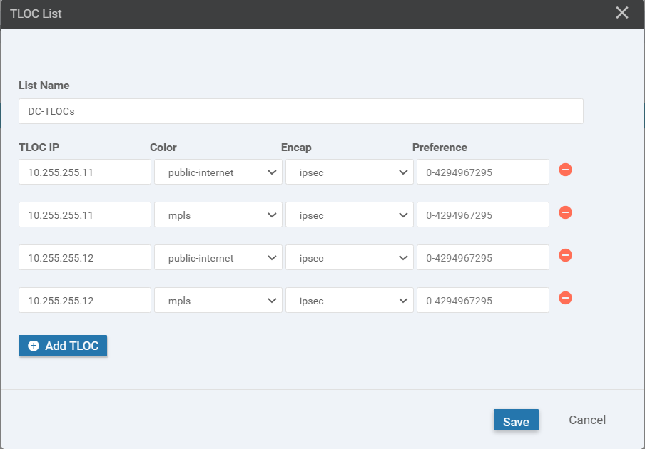
Click on TLOC on the left-hand side then click on New TLOC List. Give a List Name of DC-TLOCs. Specify the following values (click Add TLOC 3 times - this will add the number of rows we need)
TLOC IP Color Encap 10.255.255.11 public-internet ipsec 10.255.255.11 mpls ipsec 10.255.255.12 public-internet ipsec 10.255.255.12 mpls ipsec 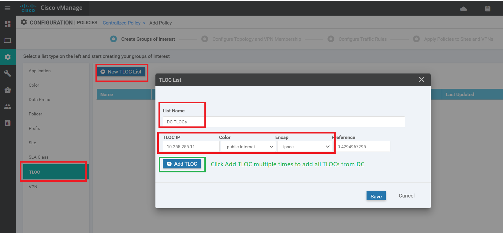
-
The DC-TLOCs list should look like the following image. Click on Next
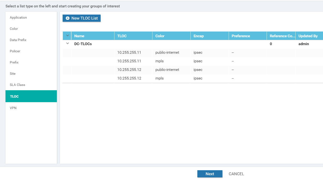
We will pause here since configuration of the Network Constructs is complete for our Control Policy. These will be used as building blocks for our policies. Configuration of the policy itself will continue in the next section (carrying on from the page we’re at in the vManage GUI).
-
-
- Creating the Policy
-
- Adding a Custom Control Policy
- Activity Verification
Adding a Custom Control Policy
Continuing from the previous section, let’s build out our Custom Control Policy to enforce a Hub and Spoke Topology on VPN 20
-
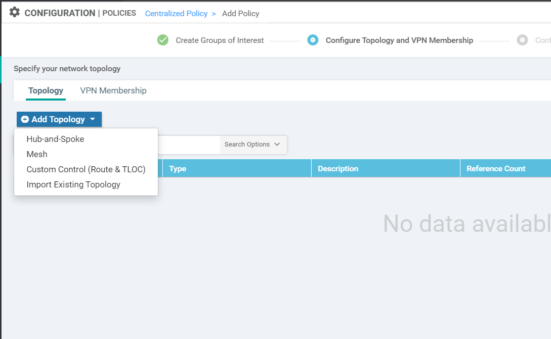
You should be at the Configure Topology and VPN Membership page after the previous section. Click on Add Topology and choose Custom Control (Route & TLOC)
-
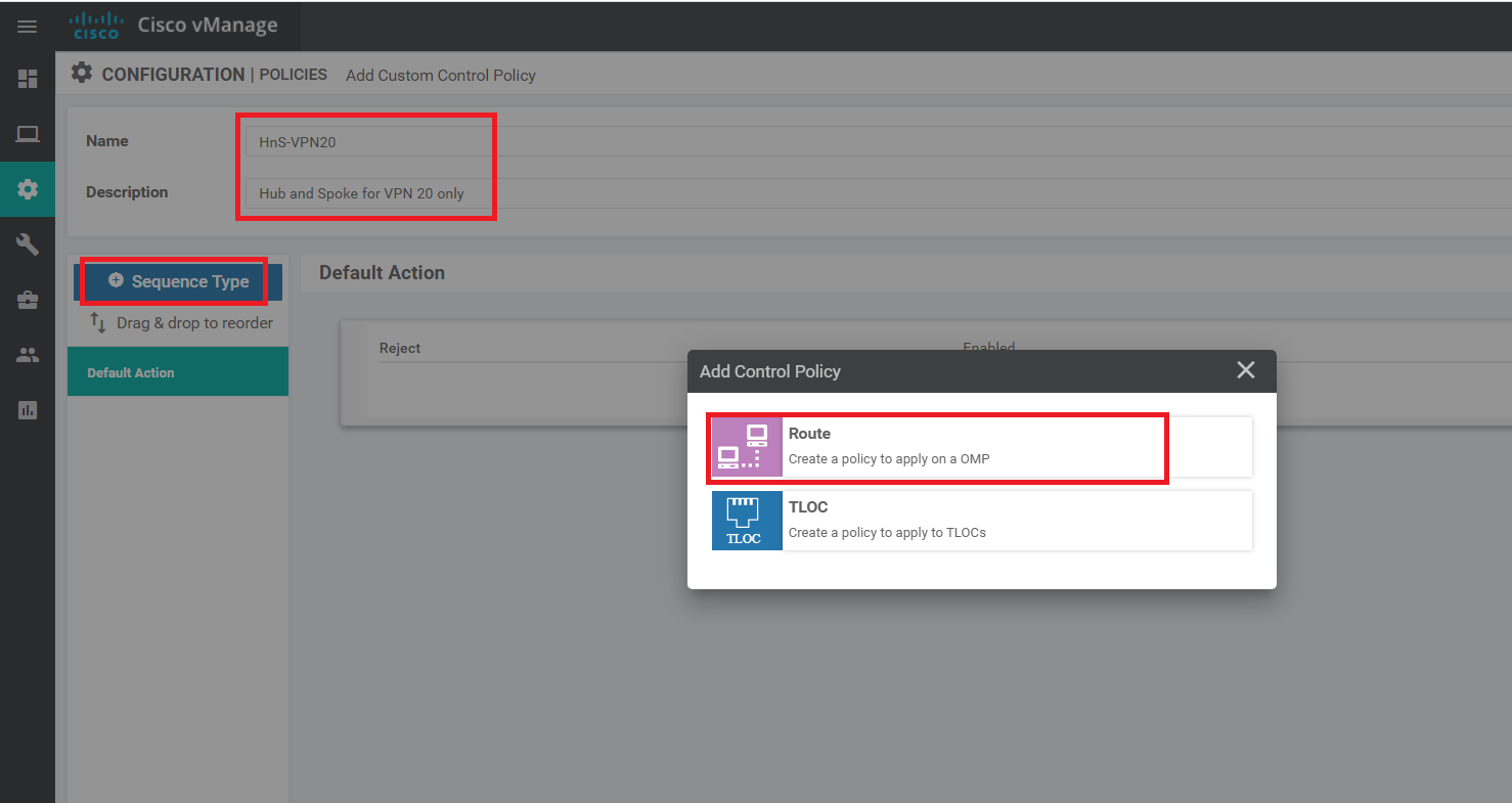
Specify a Name of HnS-VPN20 with a Description of Hub and Spoke for VPN 20 only. Click on Sequence Type and choose to add a Route Control Policy
-
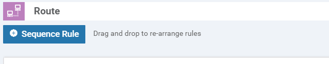
Click on Sequence Rule to add a new rule
-
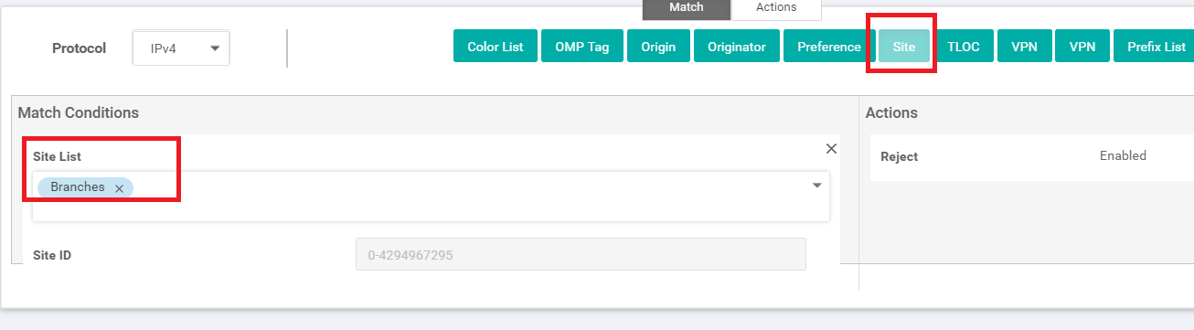
Under Match click on Site and populate Branches in the Site List (this is one of the Site Lists we had created before)
-
Still under Match, click on VPN and choose PoS in the VPN List
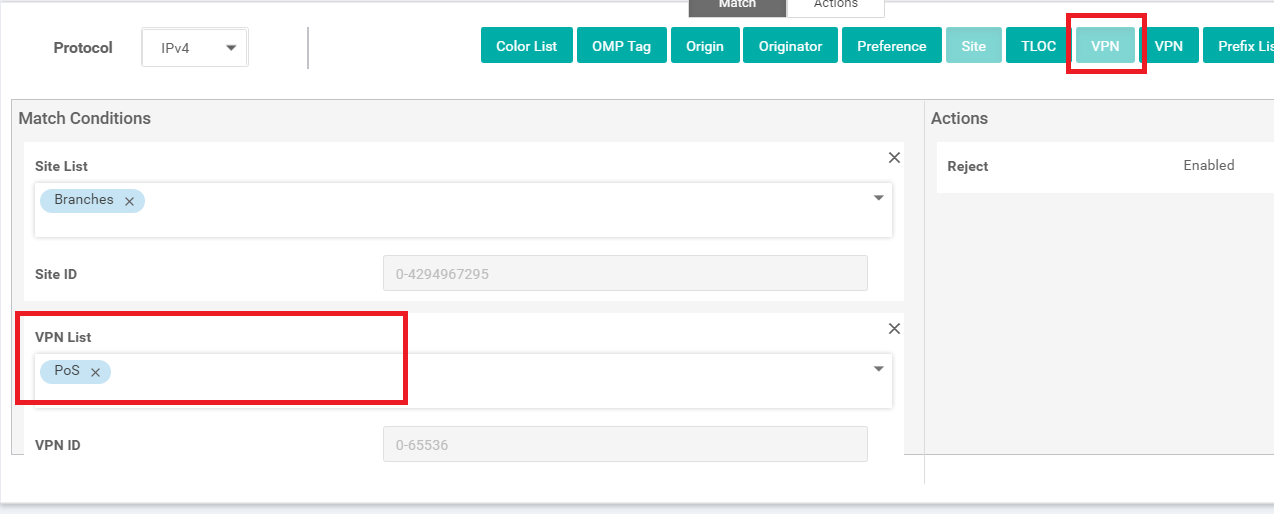
Through these two match conditions, we have specified that this rule applies to the site list Branches (which contains Site IDs 20, 30, 40 and 50) and to the PoS VPN (which has VPN 20 in it)
-
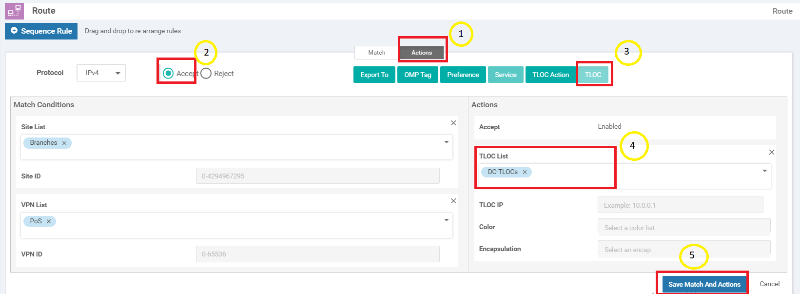
Move over to the Actions tab and click on Accept. Then click on TLOC and populate DC-TLOCs in the TLOC List. Click on Save Match and Actions
-
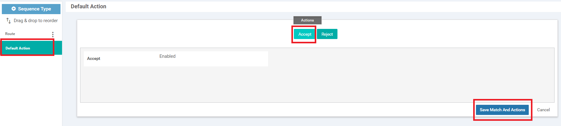
Go to the Default Action and click on Accept. Click Save Match and Actions
-
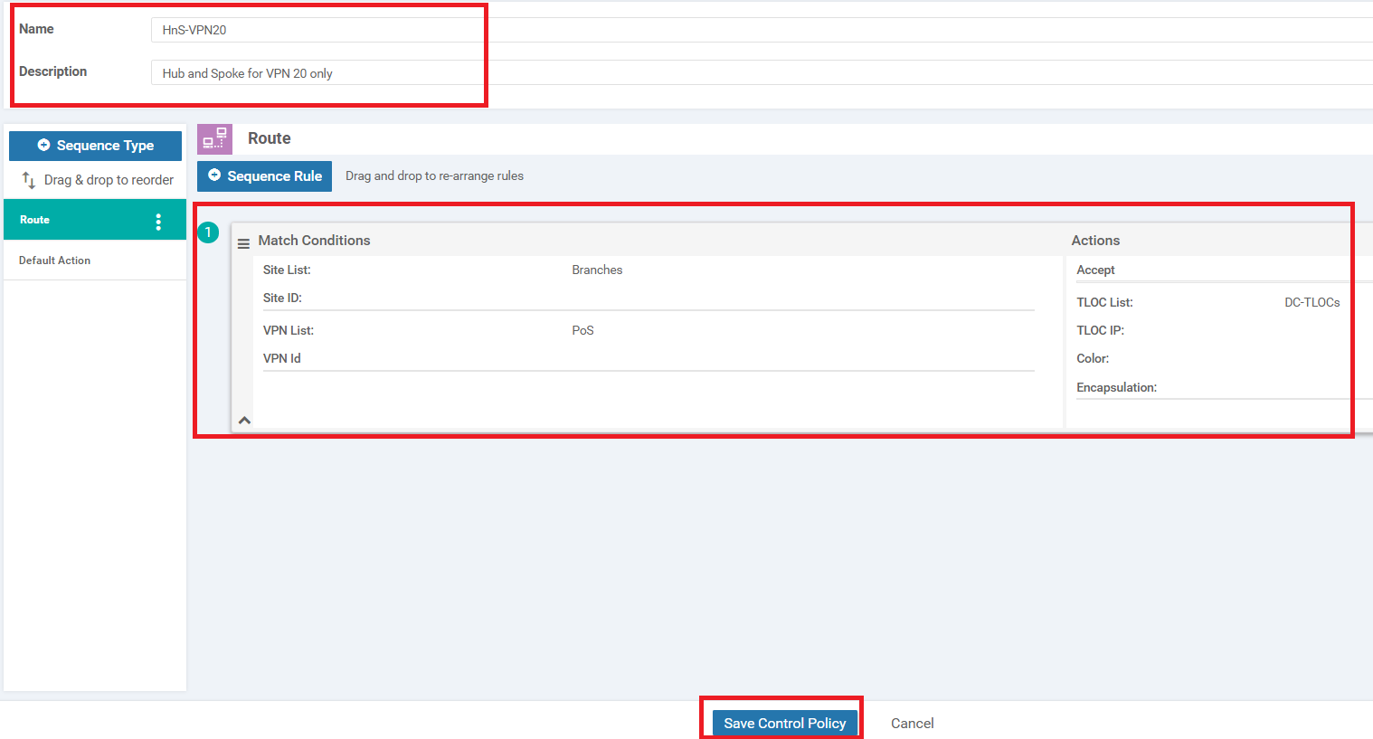
The HnS-VPN20 policy should look like the image below. Click on Save Control Policy
-
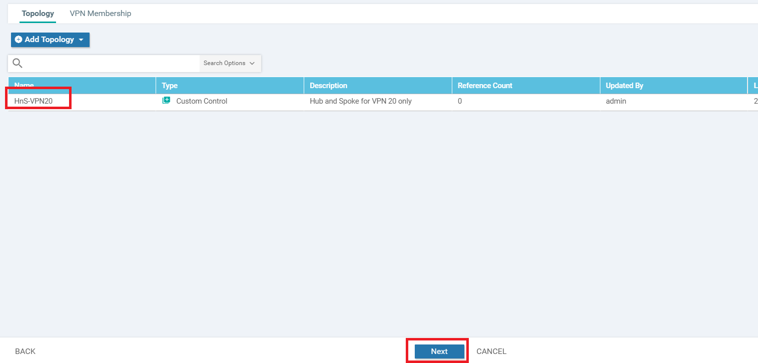
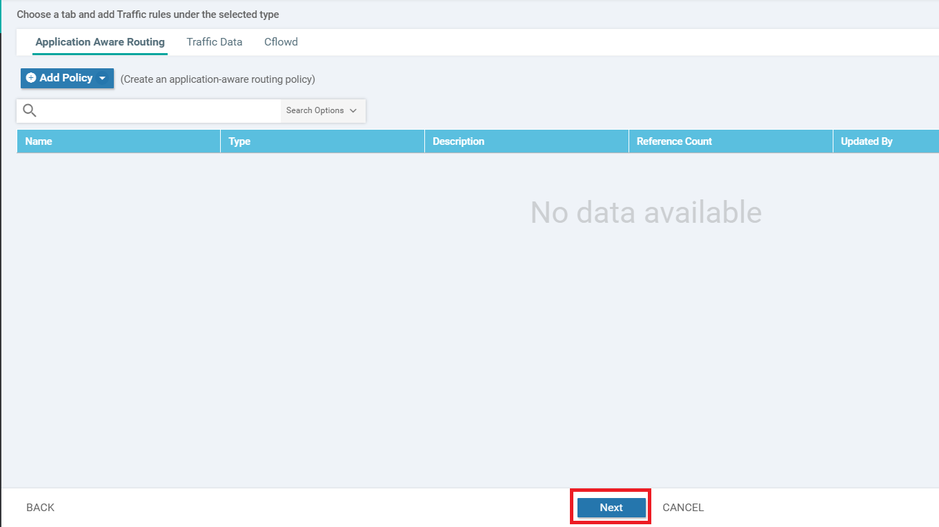
Click on Next since we don’t want to add any more Policies and then Next again (since we aren’t doing any Application Aware Routing, Data Policies or Netflow policies as of now)
-
You should be presented with a screen which asks for a Policy Name, among other things. This can be a bit confusing since we just gave a Policy Name before (called HnS-VPN20). The easiest way to wrap your head around this is think of creating a Master Policy and before we can name this Master Policy, we are asked to create Sub-Policies in it. So far, we have just created a Sub Policy and given it a name. At this point, we are being asked to give a name to our Master Policy, which will then need to be applied.
Enter a Policy Name of Hub-n-Spoke-VPN20-only and give a Policy Description of Hub and Spoke policy for VPN 20 only. Click on New Site List under HnS-VPN20 and populate Branches in the Outbound Site List. Click on Add
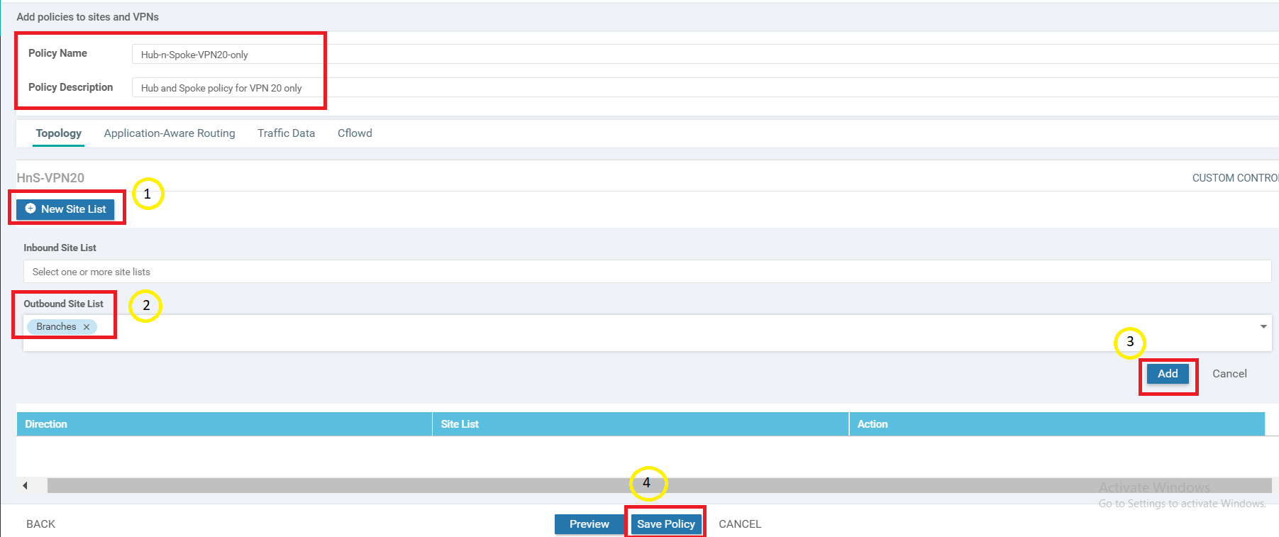 Tip: Control Policies (such as the one you just built) are enforced by vSmart. Hence, the policy you just created is from the perspective of vSmart. The application of this policy is enforced in an outbound direction towards branch sites (i.e. Branches Site List). Think of how a BGP Route-Reflector would modify the next-hop of routes it receives before sending them back out to neighbors.
Click on Save Policy
-
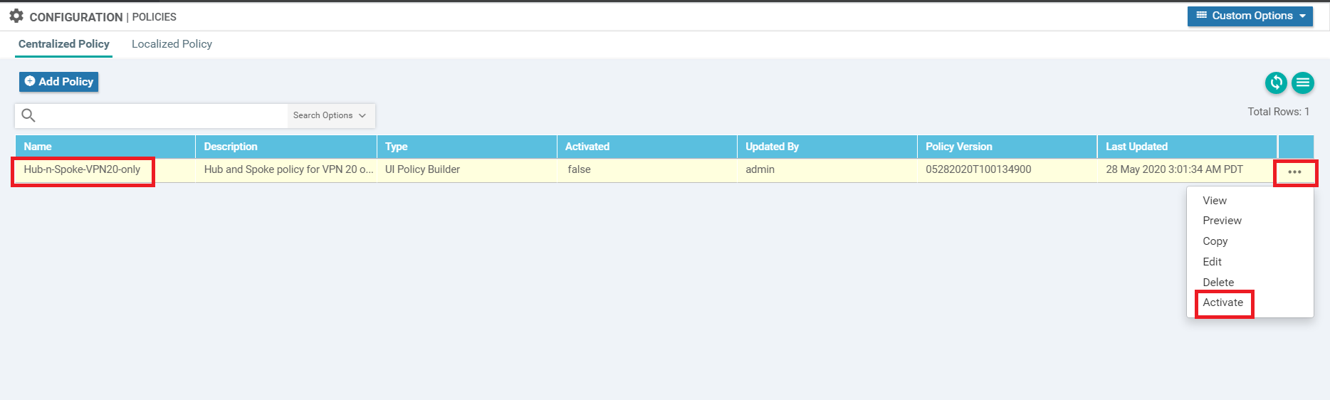
Back at the main Policy page, we should see the Hub-n-Spoke-VPN20-only Master Policy created. Click on the three dots next to it and choose to Activate the policy
-
Confirm the activation by clicking on Activate
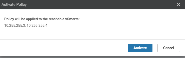
This completes our policy creation and activation. We will verify functionality in the upcoming section.
-
-
-
-
-
- Activity Verification
Activity Verification
-
Log in to cEdge40 via Putty and run
show ip route vrf 20. When compared to the output of this command taken before we applied our policy, we see that all routes are now pointing to the DC-vEdges. Check Step 5 of Overview for the earlier output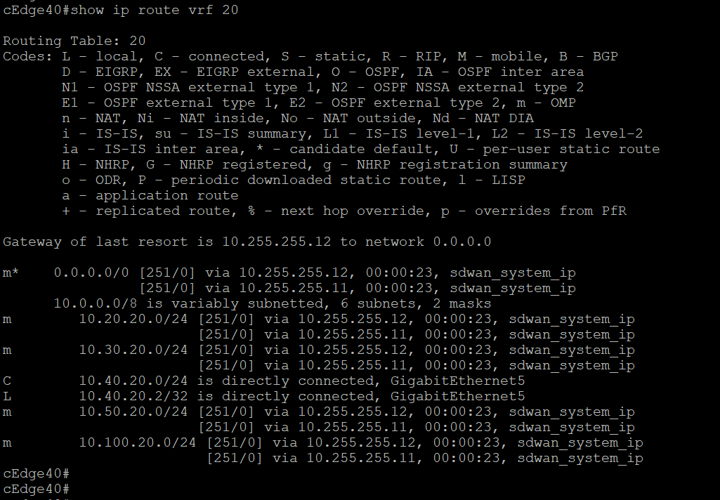
-
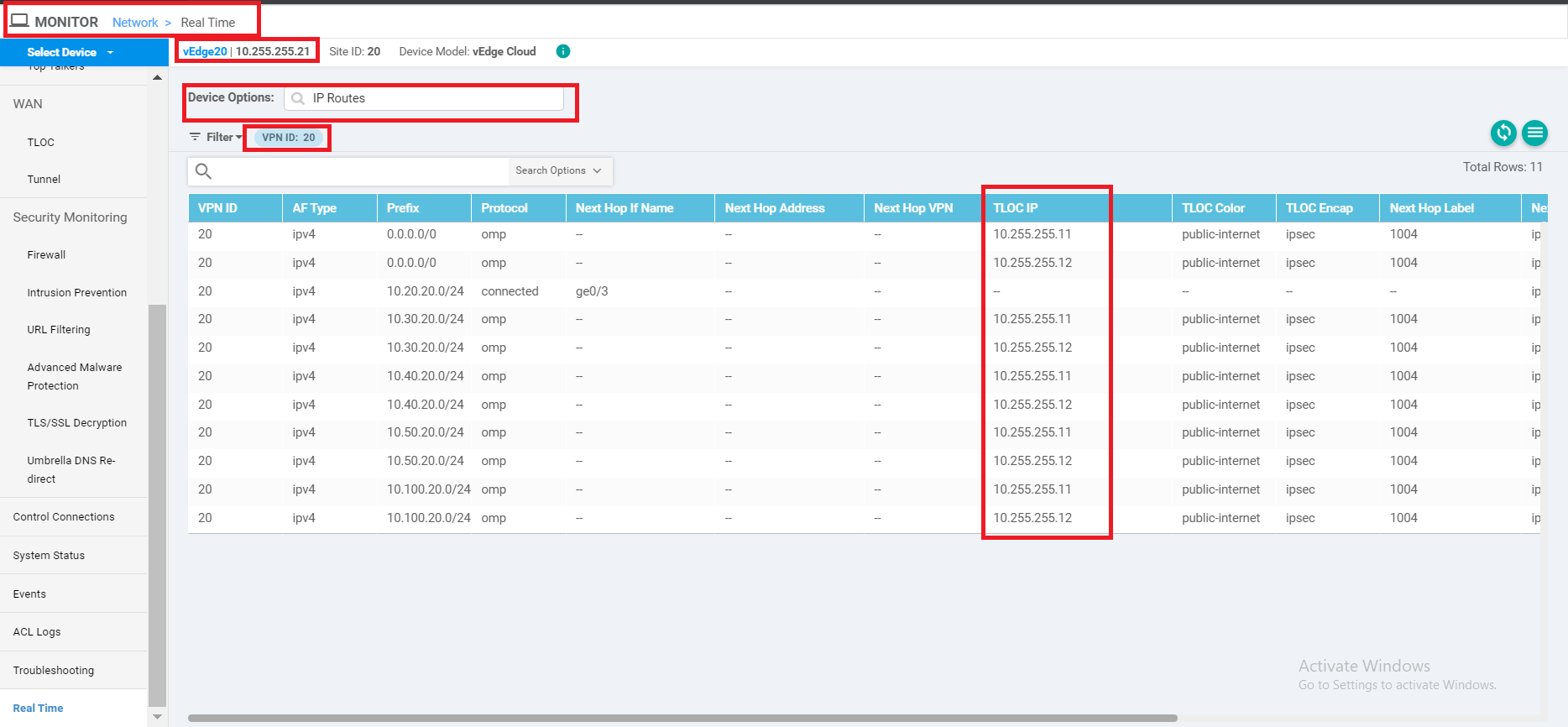
On the vManage GUI, go to Monitor => Network and click on vEdge20. Scroll down on the left-hand side and click on Real Time. Enter IP Routes in Device Options and choose to Filter. Filter on the basis of VPN ID 20. We will notice similar output as what was seen for cEdge40
-
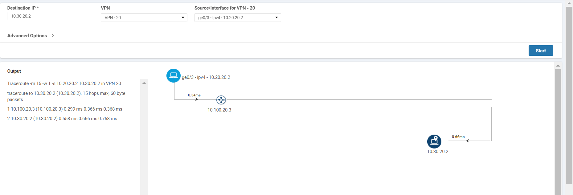
Go to Troubleshooting and choose Trace Route. Enter the Destination IP as 10.30.20.2 with a VPN of VPN - 20 and a Source/Interface of ge0/3. Traffic is now reaching the destination via the DC-vEdge
-
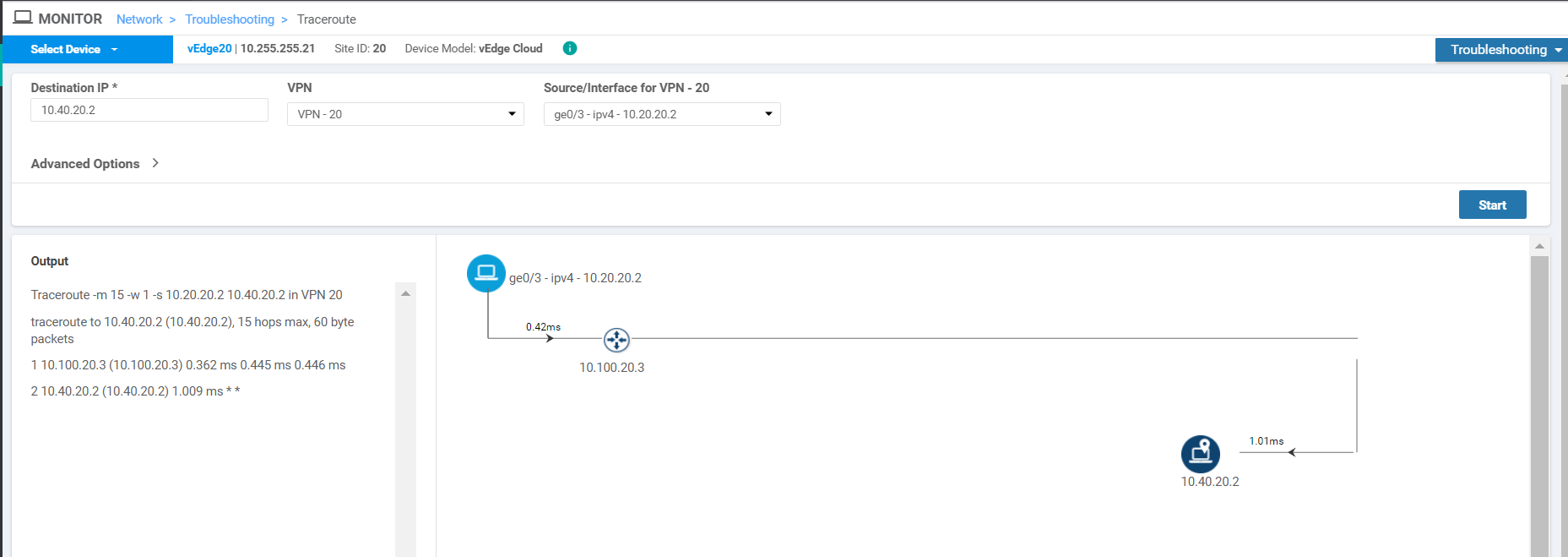
Run the traceroute for 10.40.20.2 and we see that traffic is being routed through the DC-vEdge in this case as well
-
Try to do a traceroute to 10.40.10.2, changing the VPN to VPN - 10 and the Source/Interface to ge0/2 and we will notice that VPN 10 still has full mesh connectivity

Thus, all traffic from VPN 20 in the Branches is being steered to the DC-vEdges in a Hub and Spoke topology, whereas traffic still utilizes a Mesh topology for other VPNs.