- Pre-Configuration
- Adding the Policy
- Setting up Site Lists
- Adding Custom Control policies
- Policy for Traffic from Site 20 to the Regional Hub
- Policy for Traffic from the Fabric to Site 20
- Saving and Activating the Policy
- Verification
Pre-Configuration
In this section, we will ensure that whenever communication has to happen in/out of Site 20, it goes through Site 30. This means there will be two parts to the configuration - how Site 20 talks to other sites, and how other sites talk to Site 20. Site 30 will function as a Regional Hub for Site 20. Given below is the traffic flow we’re looking to achieve.
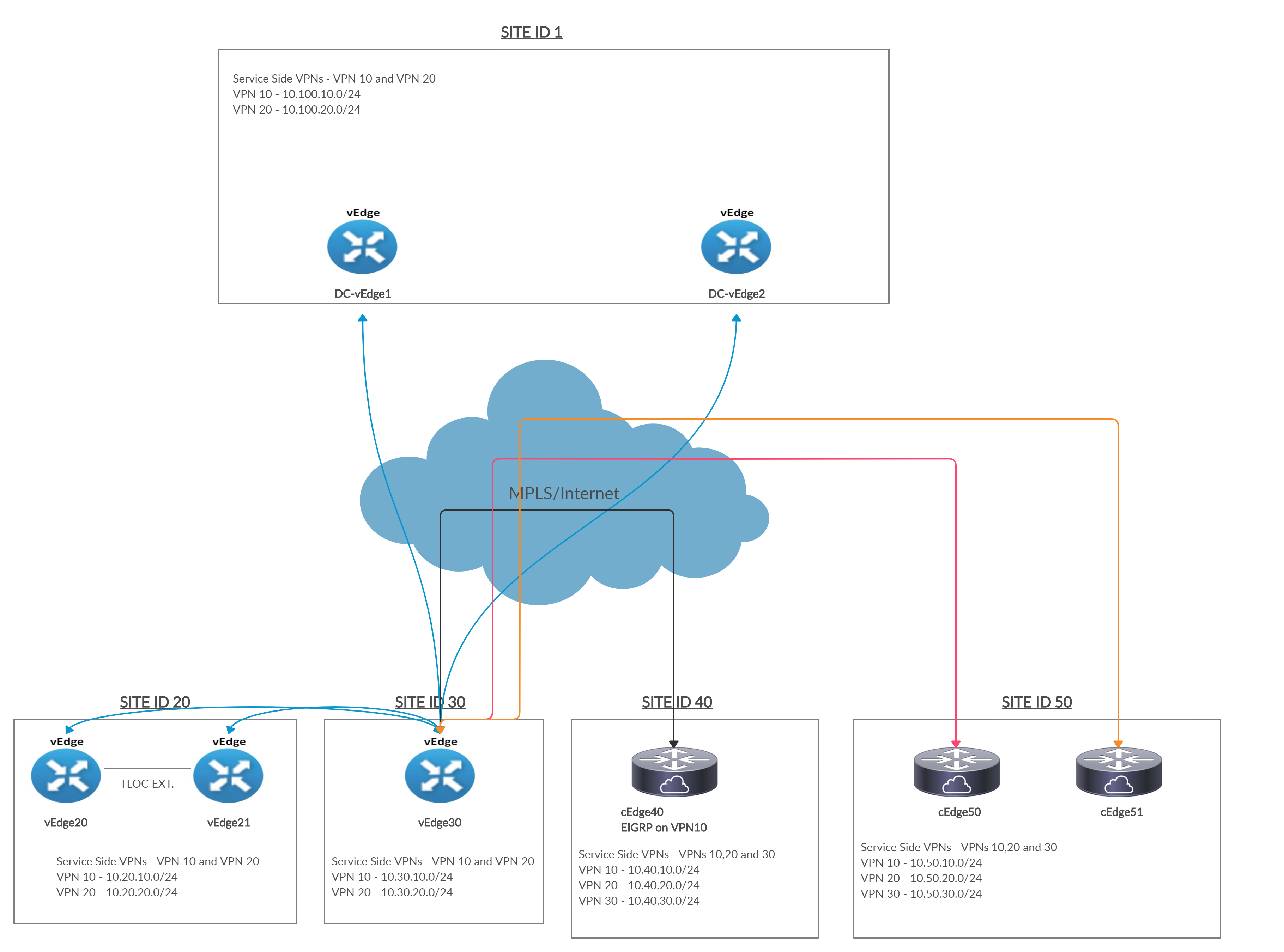
Notice that all sites communicate to Site 20 via Site 30. Conversely, Site 20 punts all outbound traffic to Site 30.
-
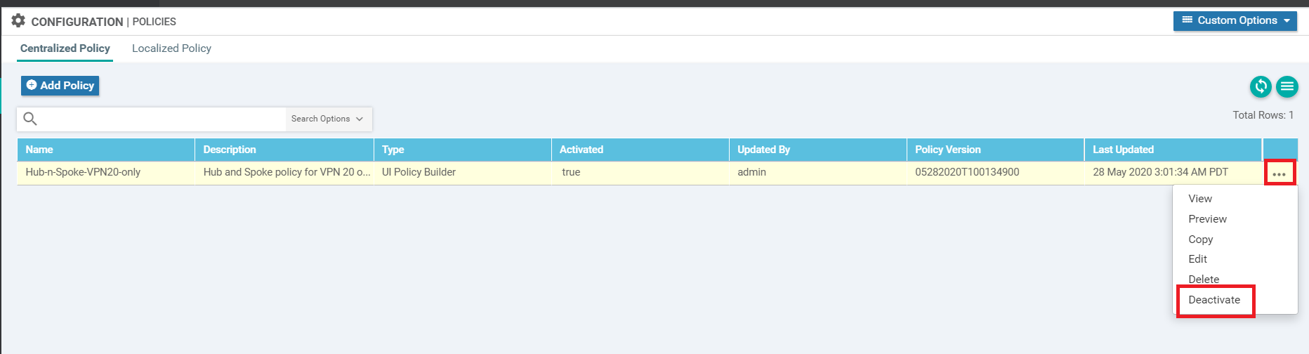
We will first deactivate the Hub and Spoke policy created for VPN 20. On the vManage GUI, navigate to Configuration => Policies and click on the three dots next to the Hub-n-Spoke-VPN20-only policy. Choose to Deactivate it
-
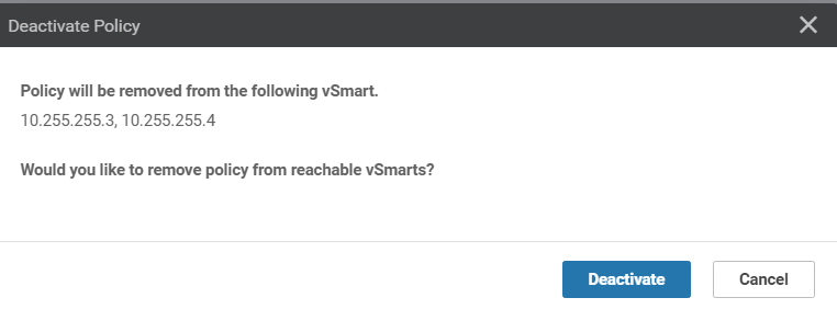
Confirm the Deactivation
-
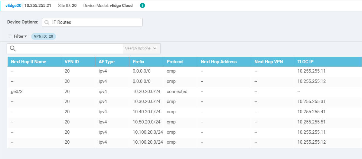
Verify that traffic for VPN 20 is now flowing per the default Mesh topology. Navigate to Monitor => Network and click on vEdge20. Scroll down on the left-hand side to Real Time and enter IP Routes in the Device Options. Choose to Filter on the basis of VPN ID 20
-
- Adding the Policy
- Setting up Site Lists
- Adding Custom Control policies
- Policy for Traffic from Site 20 to the Regional Hub
- Policy for Traffic from the Fabric to Site 20
- Saving and Activating the Policy
- Verification
Adding the Policy
Setting up Site Lists
-
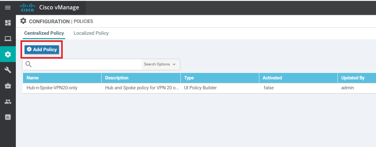
Go to Configuration => Policies and click on Add Policy
-
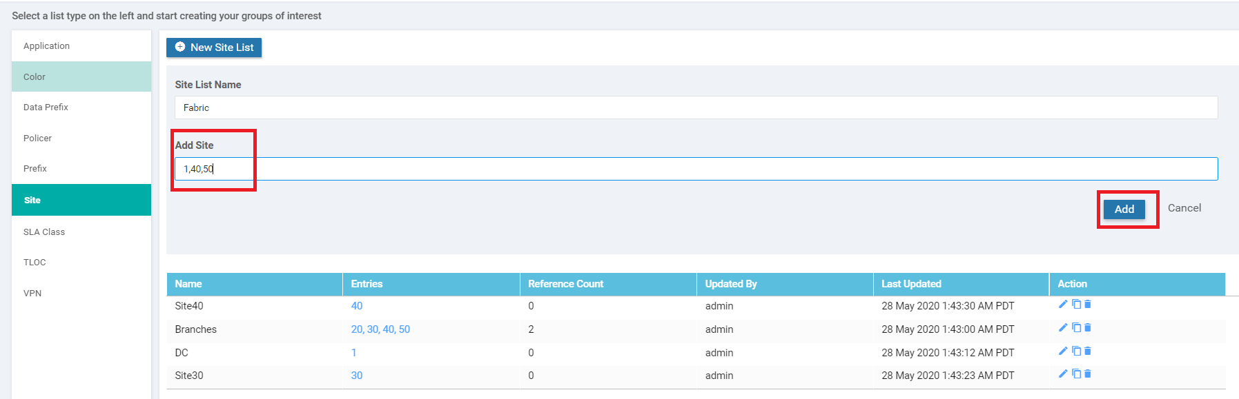
Click on Site and choose to add a New Site List. Populate the Site List Name as Fabric and Add Site of 1,40,50 (i.e. all the Sites other than the Regional Hub and Regional Spoke sites). Click on Add
-
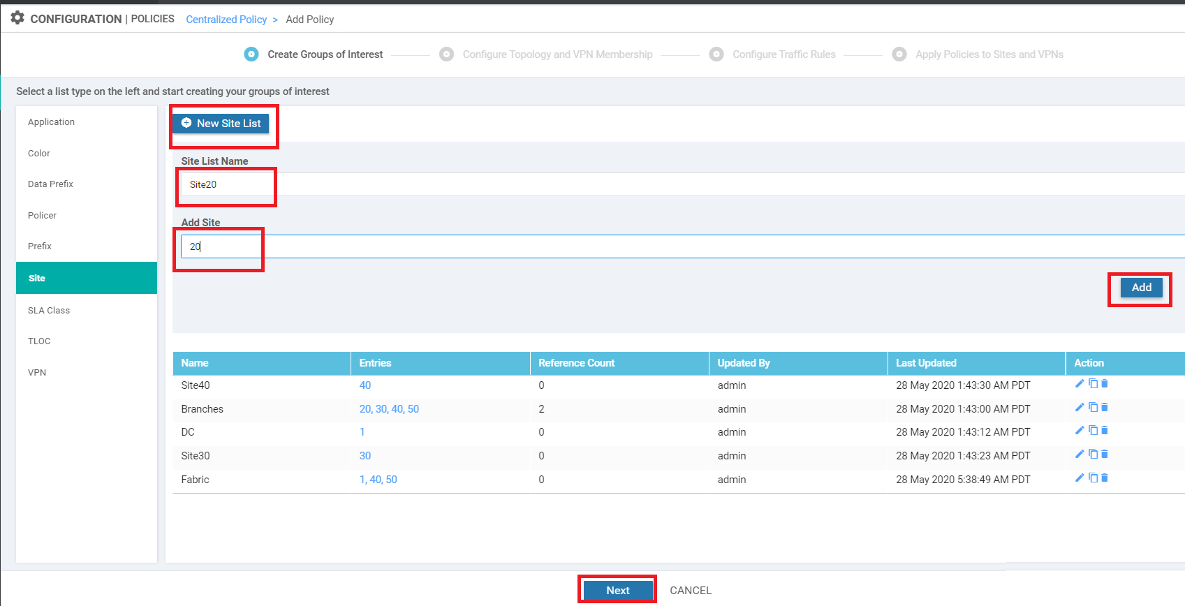
Click on New Site List again and give this Site List a Name of Site20 with an Add Site of 20. Click on Add. Click on Next to move on to the Configure Topology and VPN Membership page, which we will continue configuring in the next section
-
- Adding the Policy
-
- Adding Custom Control policies
- Policy for Traffic from Site 20 to the Regional Hub
- Policy for Traffic from the Fabric to Site 20
- Saving and Activating the Policy
- Verification
Adding Custom Control Policies
We will be adding two policies in this section - one for traffic destined to the rest of the network from Site 20 and one for traffic destined to Site 20.
Policy for Traffic from Site 20 to the Regional Hub
-
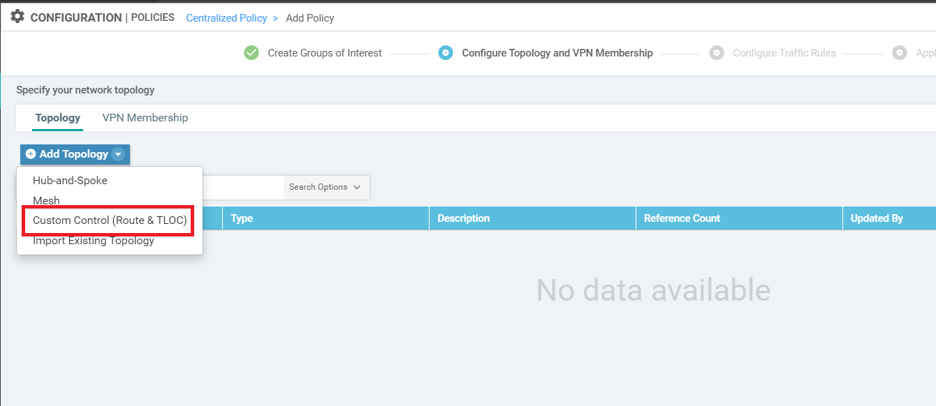
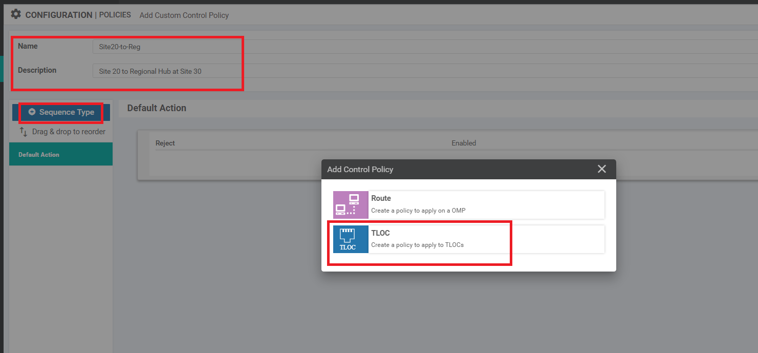
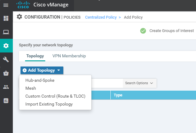
Continuing from the previous section, click on Add Topology and choose to add a Custom Control (Route and TLOC) topology
-
Give this Control Policy a Name of Site20-to-Reg and a Description of Site 20 to Regional Hub at Site 30. Click on Sequence Type and choose TLOC
-
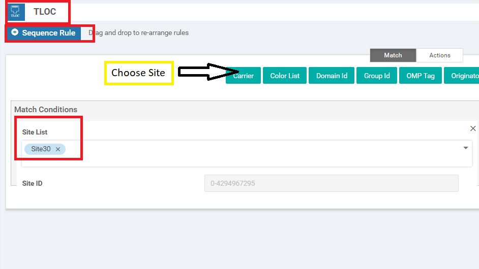
Choose to add a Sequence Rule and click on Site under Match. Populate the Site List as Site30
-
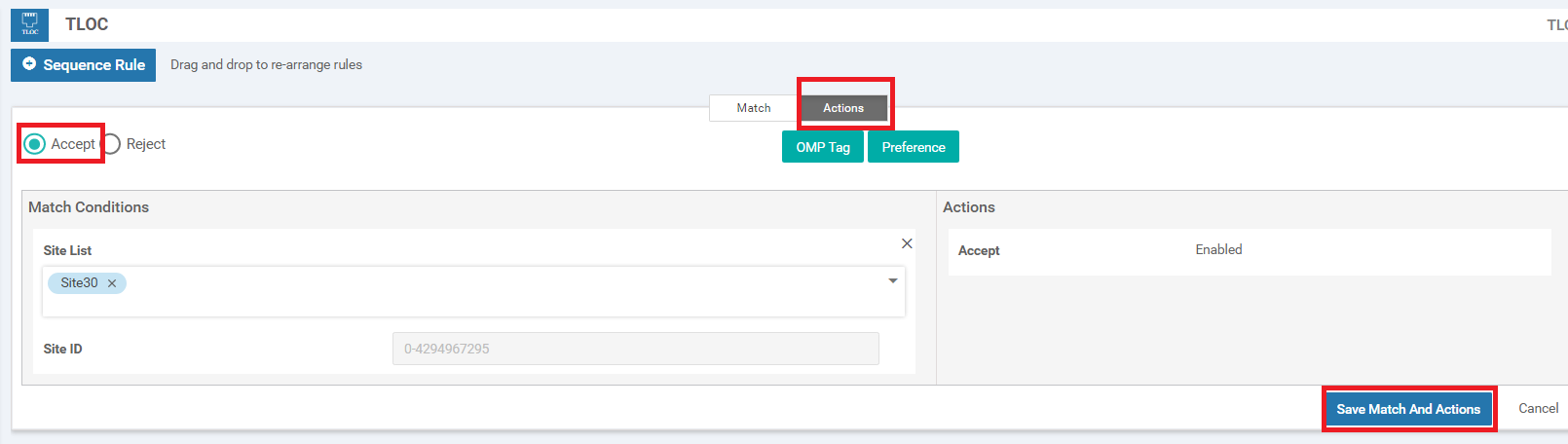
Go to the Actions tab and choose Accept. Click on Save Match and Actions
-
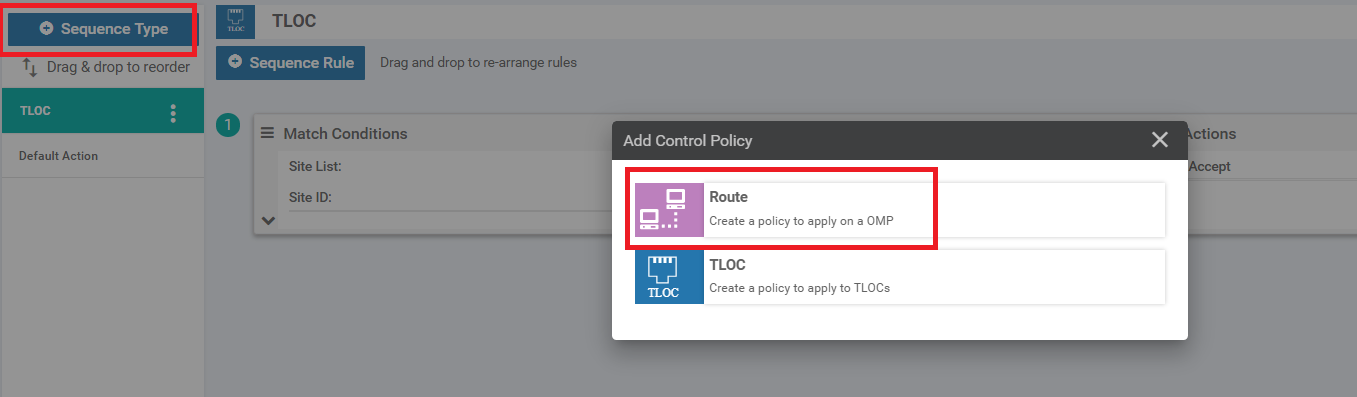
Click on Sequence Type again and this time choose Route
-
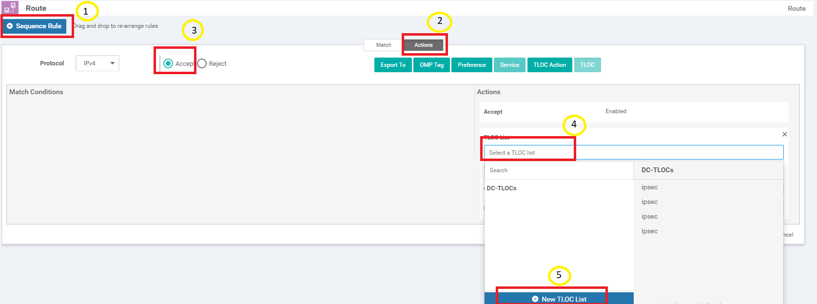
Click on Sequence Rule and go to the Actions tab. Click on Accept and click on TLOC. Click on the drop down for selecting a TLOC List and click on New TLOC List
-
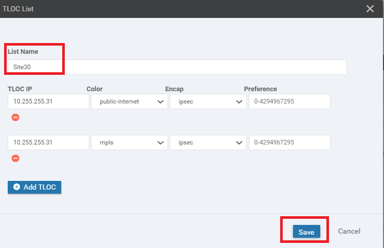
Enter Site30 as the List Name and choose to Add TLOC. This should give two rows. The TLOC IP is 10.255.255.31 (in both rows) and the Encap is ipsec. One row should have the color public-internet whereas the other row should have mpls. Click on Save
-
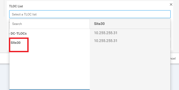
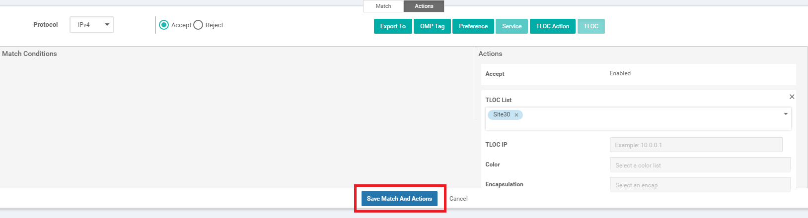
Click on the drop-down for the TLOC List and choose the Site30 List we just created. Click on Save Match and Actions
-
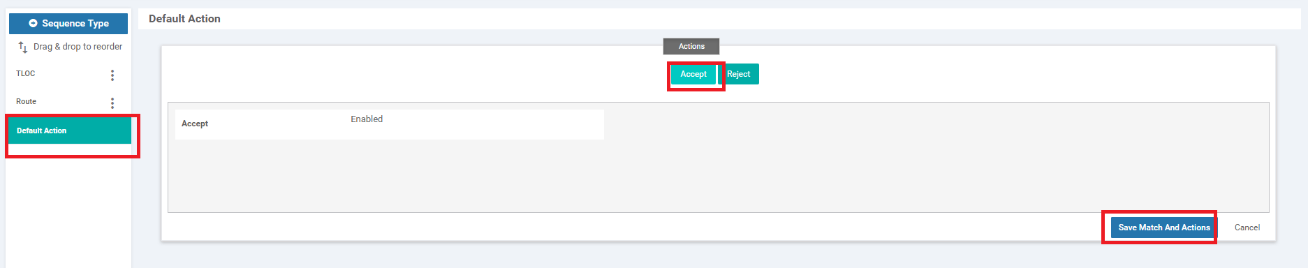
Make sure the configuration looks like the image given below and click on Save Control Policy. Note that there are two Sequence Types - a TLOC and a Route, along with the Default Action
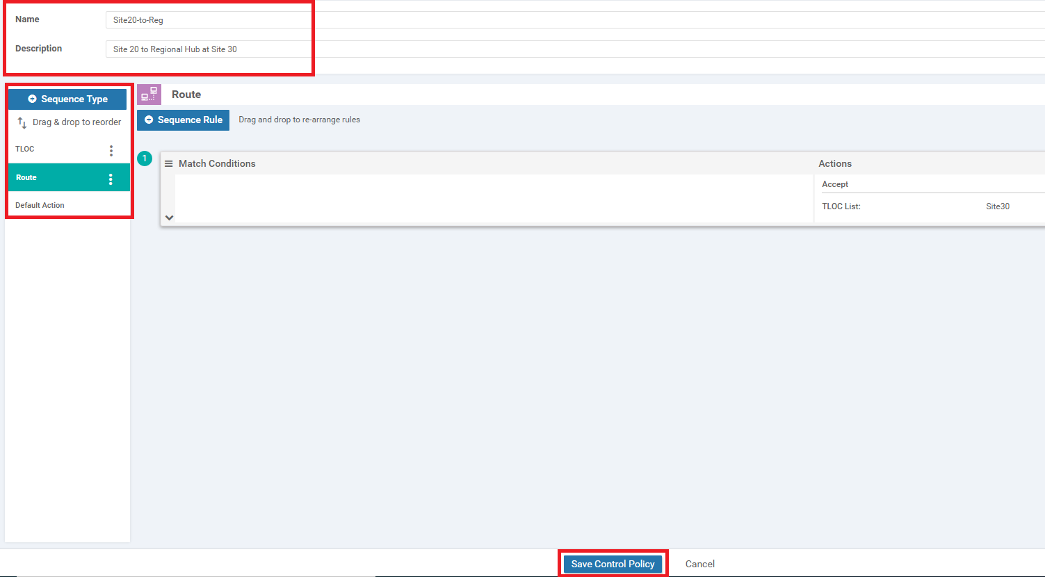
Continue with the next section for configuring another Control Policy.
-
- Adding the Policy
-
- Adding Custom Control policies
-
- Policy for Traffic from the Fabric to Site 20
- Saving and Activating the Policy
- Verification
Policy for Traffic from the Fabric to Site 20
-
Back at the Configure Topology and VPN Membership page, click on Add Topology. We will add another Custom Control (Route & TLOC) policy
-
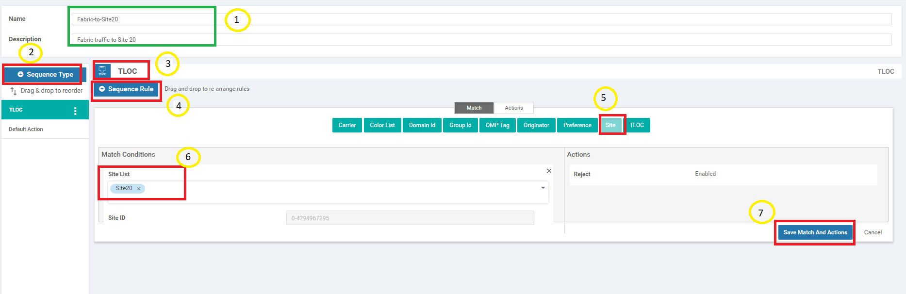
Give this Control Policy a name of Fabric-to-Site20 with a Description of Fabric traffic to Site 20. Click on Sequence Type and choose TLOC. Click on Sequence Rule and select Site under Match. Populate Site20 in the Site List. Click on Save Match and Actions since the default of Reject Enabled is what we want for this Control Policy
-
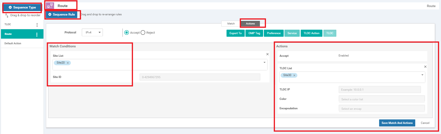
Click on Sequence Type again and choose Route. Click on Sequence Rule and choose Site under the Match tab. Populate Site20 in the Site List. Click on the Actions tab and choose Accept. Click on TLOC and populate Site30 from the TLOC List drop down. Click on Save Match and Actions
-
Click on Default Action and choose Accept. Save Match and Actions to complete configuration of this Control Policy and click on Save Control Policy
We will complete configuration of the Policy in the next section.
-
- Adding the Policy
-
-
-
-
- Saving and Activating the Policy
- Verification
Saving and Activating the Policy
-
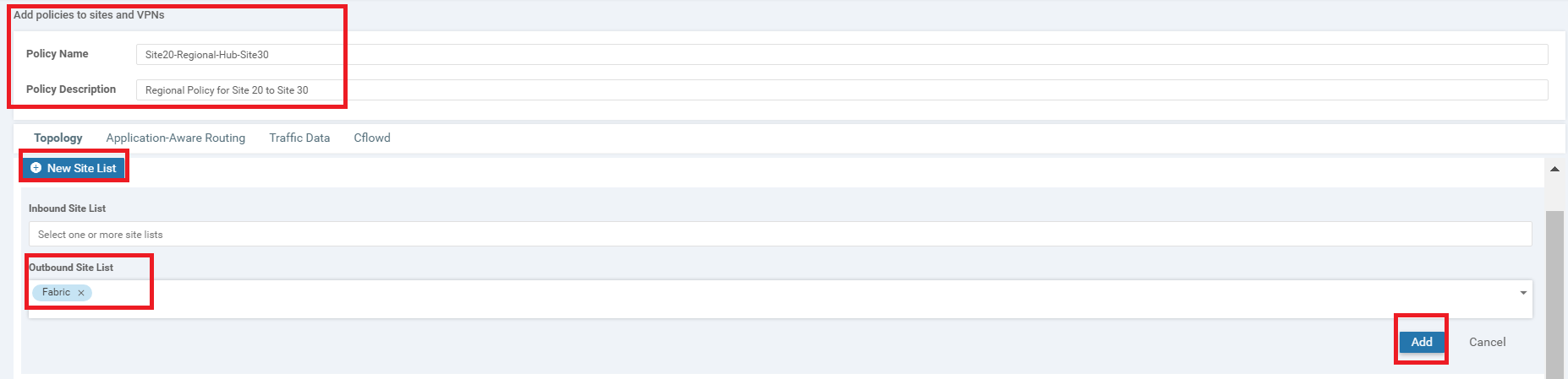
Click on Next two times from the page you’re on at the end of the previous section (this should take you to the Apply Policies to Sites and VPNs page). Enter the Policy Name as Site20-Regional-Hub-Site30 and the Description as Regional Policy for Site 20 to Site 30. Click on New Site List and populate Fabric in the Outbound Site List for the Fabric-to-Site20 Custom Control Policy. Click on Add
-
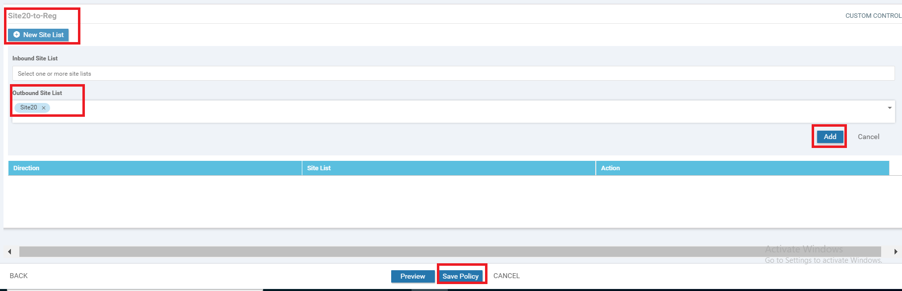
Under the Site20-to-Reg Custom Control policy, click on New Site List and populate Site20 in the Outbound Site List. Click on Add and then click on Save Policy
-
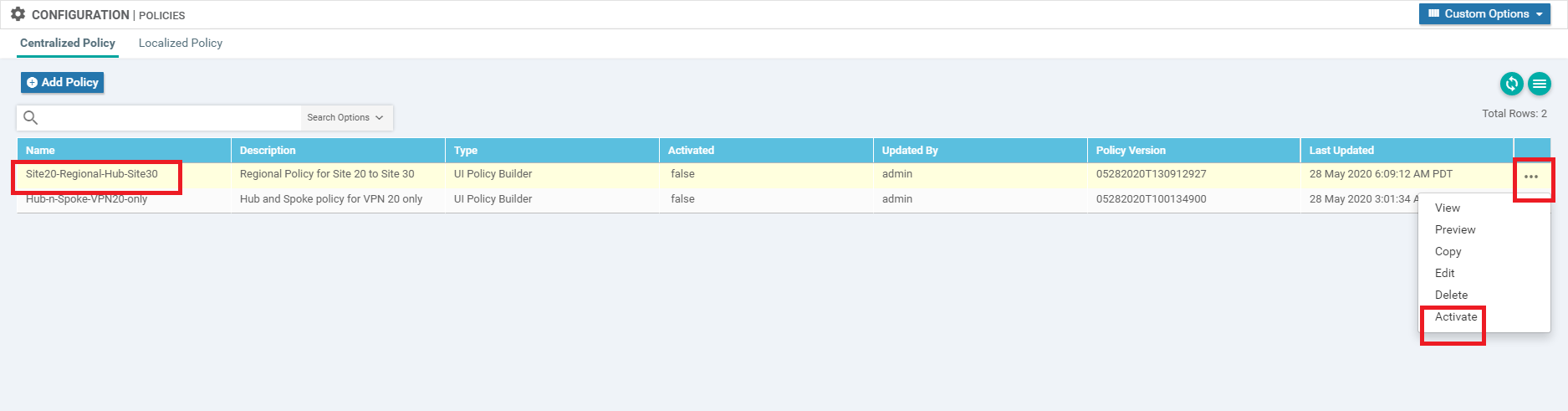
Click on the three dots next to the Site20-Regional-Hub-Site30 policy and choose to Activate it
-
Confirm the Activation
This completes the configuration of our Policy for making Site 30 a Regional Hub to Site 20. We will verify the configuration done in the next section.
-
-
-
-
-
-
-
- Verification
Verification
-
On the vManage GUI, navigate to Monitor => Network and click on vEdge20. Scroll down to Troubleshooting (on the left-hand side) and click on Trace Route. Enter the Destination IP as 10.100.10.1 with a VPN of VPN - 10 and a Source/Interface of ge0/2. Click on Start
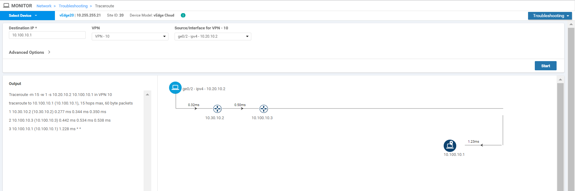
Notice that the traffic destined for the DC Service Side VPN is going through Site30 (10.30.10.2) and then getting routed over to the DC-vEdge.
-
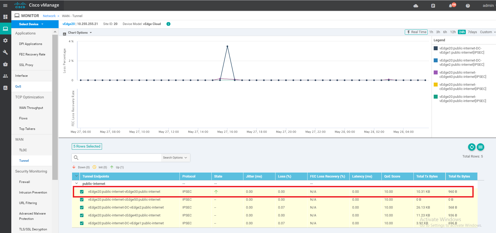
Click on Tunnel on the left-hand side and notice that vEdge20 has a single Up tunnel with vEdge30 on public-internet and one on mpls. Other tunnels are not up (as expected)
-
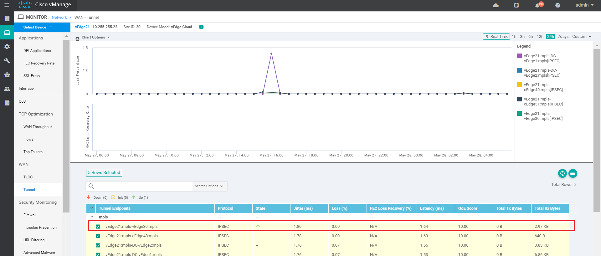
Click on Select Device in the top left-hand corner and choose vEdge21. You will notice a similar output here with respect to the Tunnels
-
Go to Troubleshooting => Trace Route and enter the same details as before (i.e. a Destination of 10.100.10.1, VPN of VPN - 10 and a Source/Interface of ge0/2). Click on Start
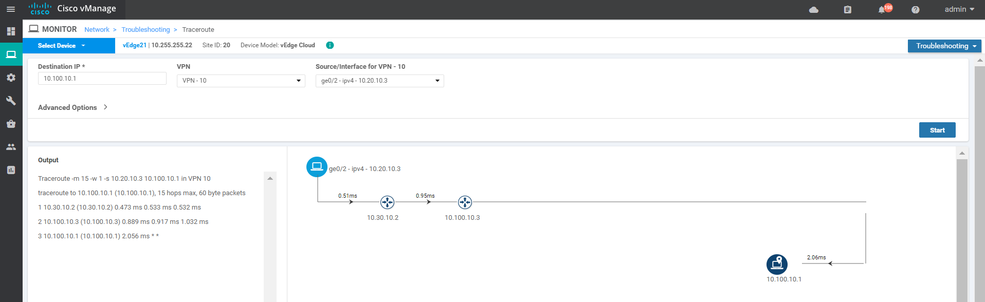
We see that traffic from vEdge21 destined for the DC-vEdge Service Side VPN traverses vEdge30 (10.30.10.2) before being punted over to the DC-vEdge
-
To verify traffic flows towards Site20, choose Select Device from the top left-hand corner and select DC-vEdge1. Enter the Destination IP of 10.20.10.2 with a VPN of VPN - 10 and a Source/Interface of ge0/2. Click on Start
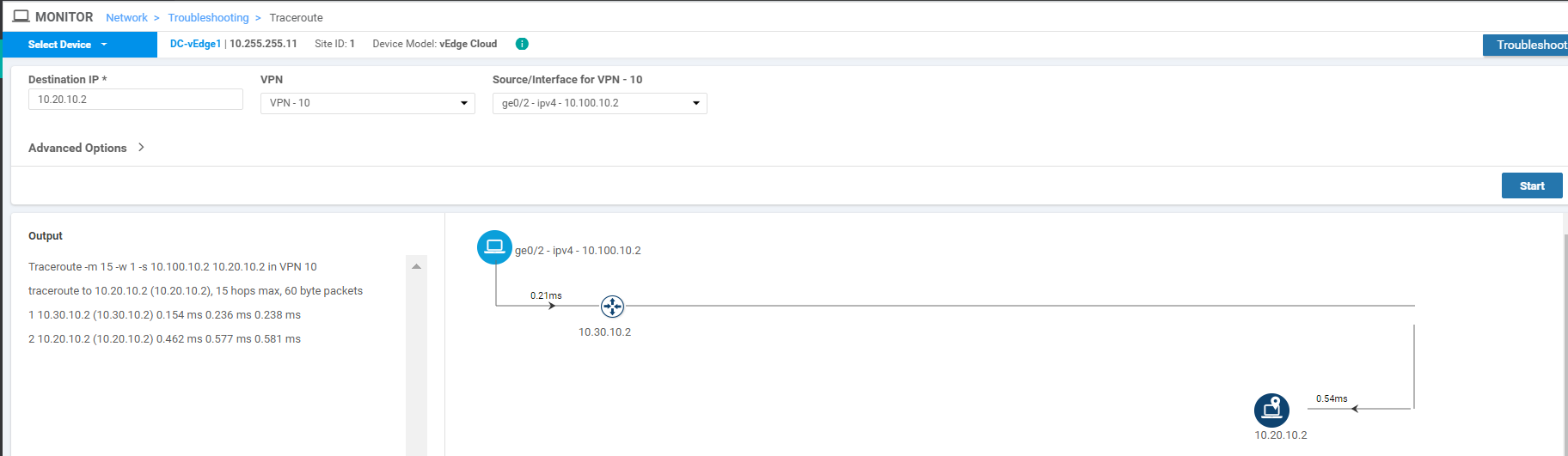
Notice that over here as well, traffic from the DC-vEdge goes to Site20 through Site30.
This completes the configuration of our Regional Hub.