- Verifying the existing lab setup
- Creating the DC-vEdge1 VM
- Overview
- Deploying the VM on vCenter
- Onboarding DC-vEdge1
- Bootstrapping DC-vEdge1 (Initial Configuration)
- Installing certificates and activating the vEdge
- Onboarding Verification
- Helpful debugs and logs
Verifying the existing lab setup
The vManage, vBond and vSmarts have been deployed and should be ready to accept control connections from vEdges and cEdges. We will start by verifying the existing setup.
-
Log in to vManage by clicking on the bookmark or navigating to https://192.168.0.6. Use the following credentials:
Username Password admin admin 
-
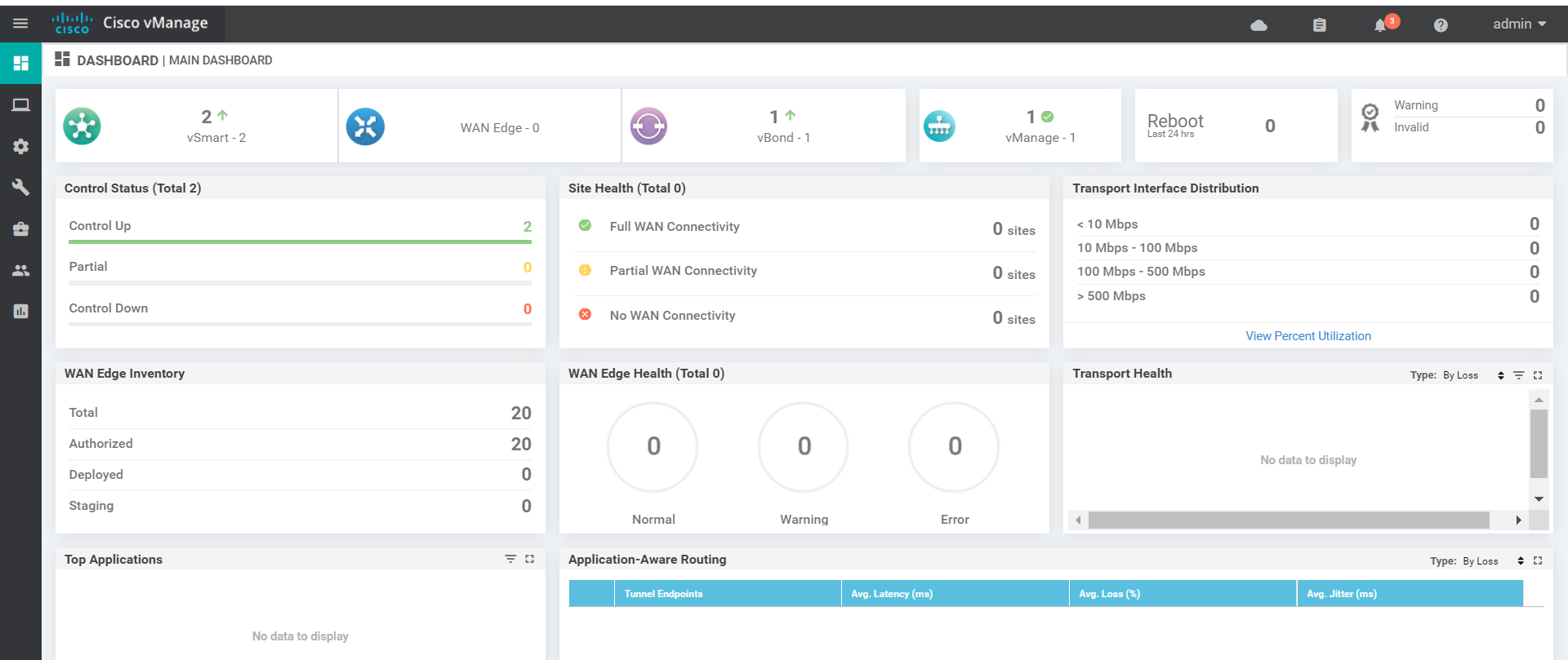
On logging in, you should see 2 vSmarts, 1 vBond and 1 vManage along the top row and 2 control planes should be up (naming convention might vary)
-
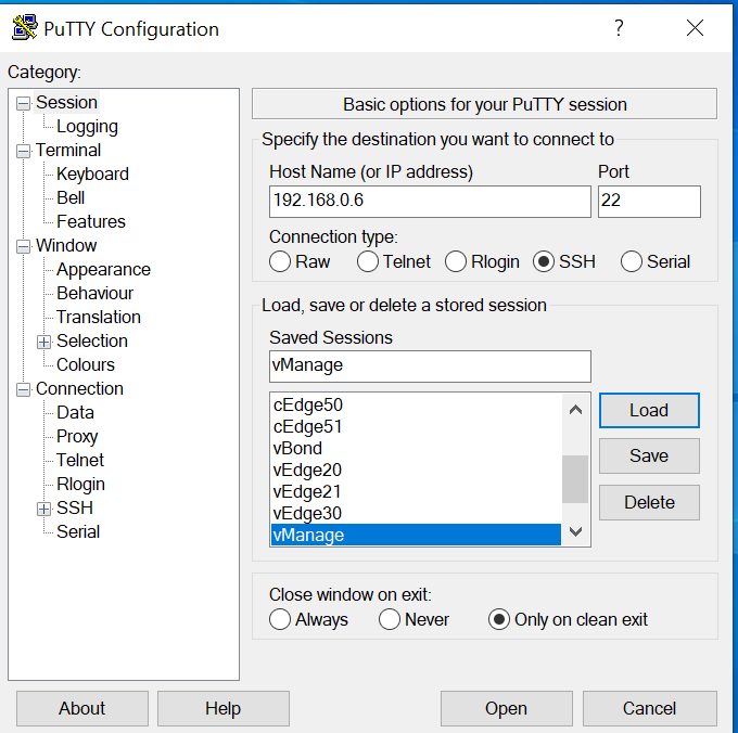
Open and log in to the vManage via the CLI - fire up Putty and double click the saved session for vManage or SSH to 192.168.0.6. Use the same credentials as the GUI.
-
Issue
show control connectionsand you should see the vManage talking to the vSmarts and the vBond.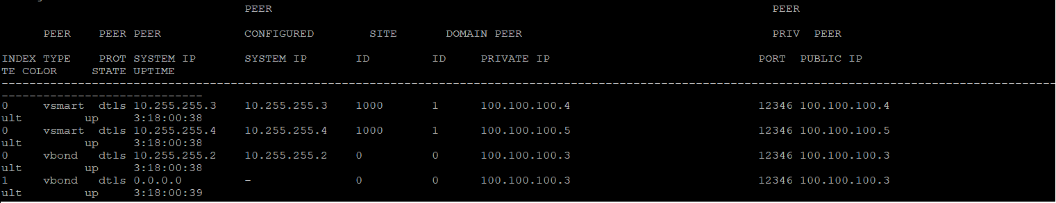
-
Additionally, you can log in to the CLI for the vBond via the saved link (and the same password as the vManage) and issue a
show orchestrator connections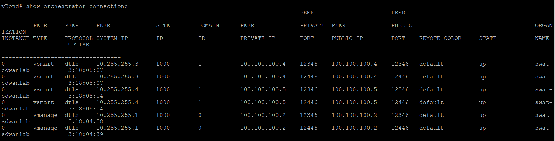
We see that the connections are up and this completes the verification activity.
-
- Creating the DC-vEdge1 VM
- Overview
- Deploying the VM on vCenter
- Onboarding DC-vEdge1
- Bootstrapping DC-vEdge1 (Initial Configuration)
- Installing certificates and activating the vEdge
- Onboarding Verification
- Helpful debugs and logs
Creating the DC-vEdge1 VM
Overview
We will be deploying a vEdge in our first site (the Data Center) via vCenter. Make note of the following information for this section. The IP Addressing will not be used for some of the Network Adapters until later. X is your POD number and is used only during vCenter related activities.
| VM Name | System IP | Network Adapter | Network | Interface | IP Address | Default Gateway |
|---|---|---|---|---|---|---|
| DC-vEdge1-podX | 10.255.255.11 | Network Adapter 1 | Management | eth0 | 192.168.0.10/24 | 192.168.0.1 |
| Network Adapter 2 | MPLS10 | ge0/1 | 192.0.2.2/30 | 192.0.2.1 | ||
| Network Adapter 3 | SiteDC_VPN10 | ge0/2 | 10.100.10.2/24 | 10.100.10.1 | ||
| Network Adapter 4 | SiteDC-VPN20 | ge0/3 | 10.100.20.2/24 | 10.100.20.1 | ||
| Network Adapter 5 | Internet | ge0/0 | 100.100.100.10/24 | 100.100.100.1 |
-
- Creating the DC-vEdge1 VM
-
- Deploying the VM on vCenter
- Onboarding DC-vEdge1
- Bootstrapping DC-vEdge1 (Initial Configuration)
- Installing certificates and activating the vEdge
- Onboarding Verification
- Helpful debugs and logs
Deploying the VM on vCenter
-
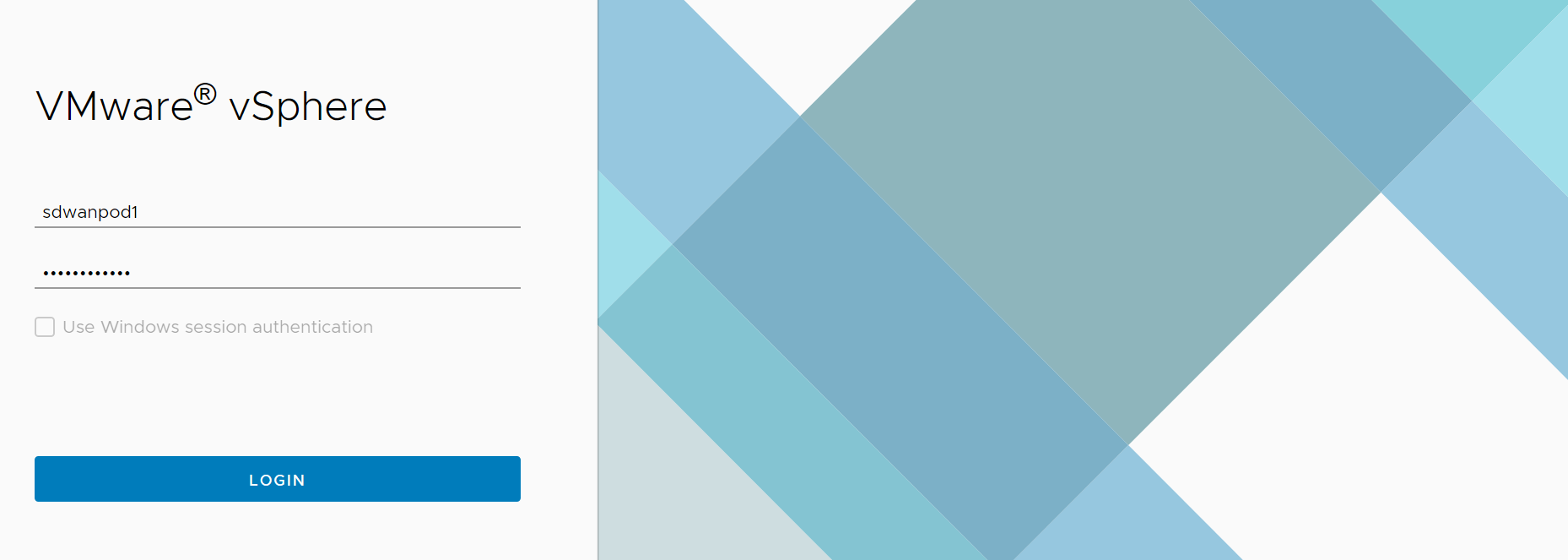
Click on the bookmark for vCenter or navigate to the following URL: https://10.2.1.50/ui if connected to the GHI DC and 10.1.1.50/ui if connected to the SJC DC. Log in with the credentials provided for your POD.
-
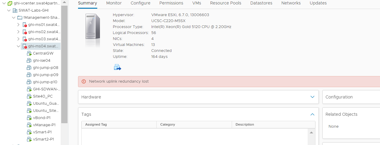
Notice that no vEdges/cEdges have been deployed on the host you’ve accessed. This is expected.
-
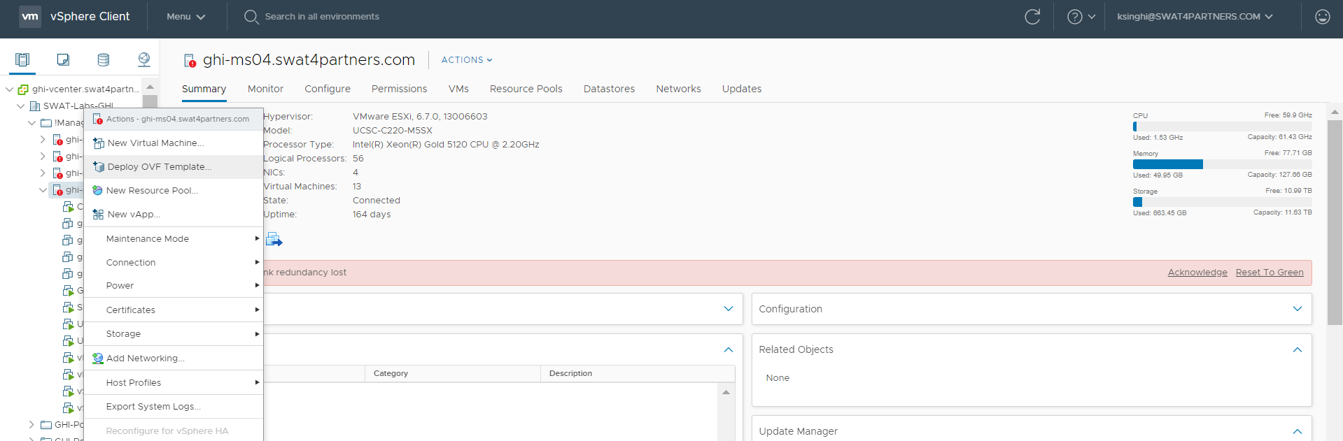
Right click on the host and choose to Deploy OVF Template
-
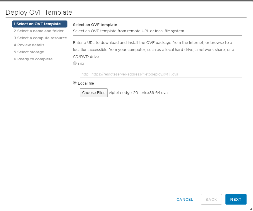
Choose the Local file option and click on Choose files. Navigate to the SD-WAN images folder and select the file beginning with viptela-edge-. Click on Next.
-
Change the Virtual Machine name to DC-vEdge1-podX and click on Next (where X is your POD number, image below doesn’t have the suffix of podX)
Note: We will only use the podX suffix over here to distinguish between different VMs in our Data Center. The rest of the guide will refer to this VM as DC-vEdge1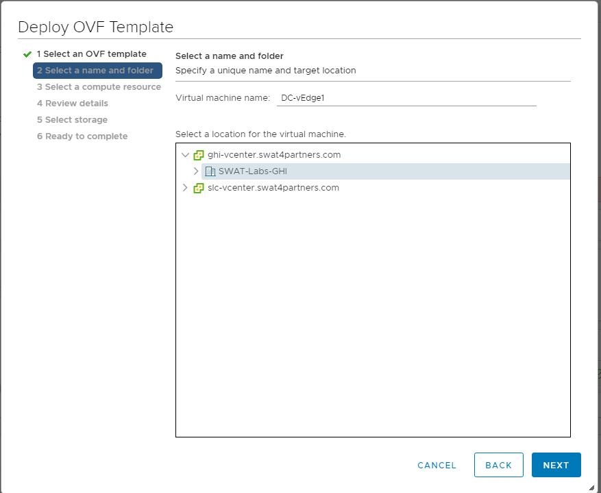
-
Select the host assigned to you (image shown as an example only) and click on Next
Note: If the screen gets stuck over here at Validating then close Chrome and open the vCenter in Internet Explorer, going through the same steps. Deployment should go through. This is a known issue with Google Chrome.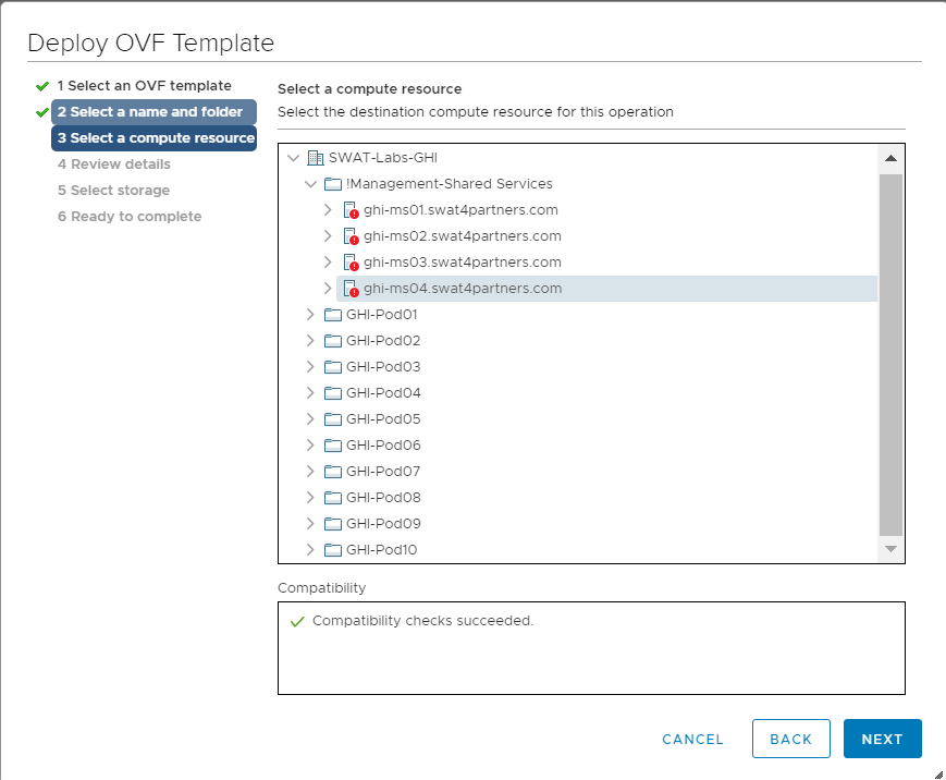
-
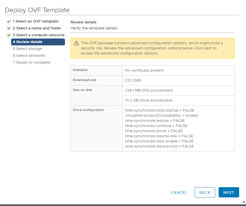
Review the details shown and click on Next
-
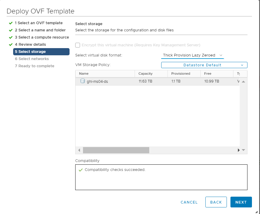
Choose the Datastore and click on Next
-
Populate the VM Networks as per the image given below
Important: Please make sure that these look exactly as shown below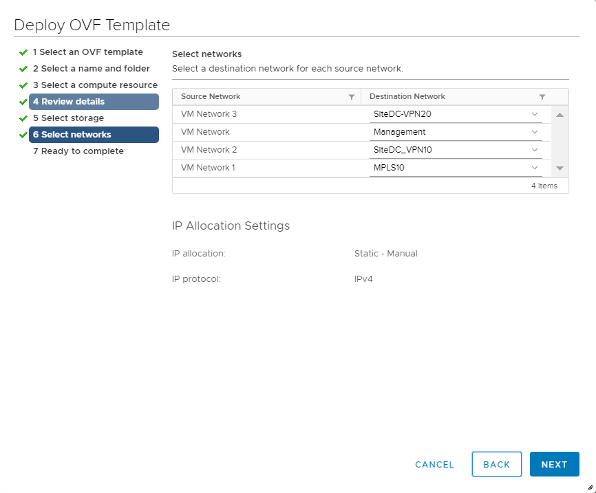
-
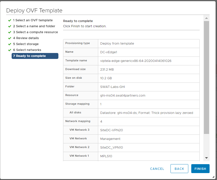
Click on Finish to deploy your DC-vEdge1 VM
-
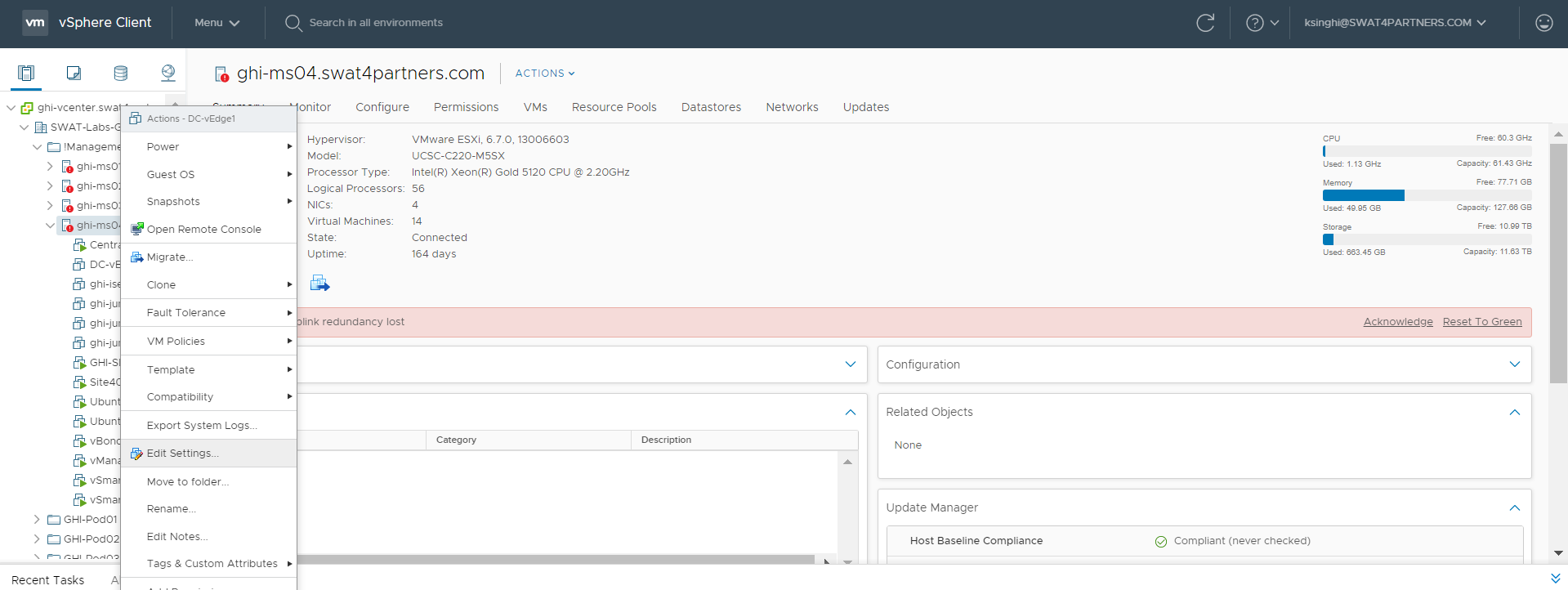
Once the VM is deployed, right click DC-vEdge1-podX and click Edit settings.
-
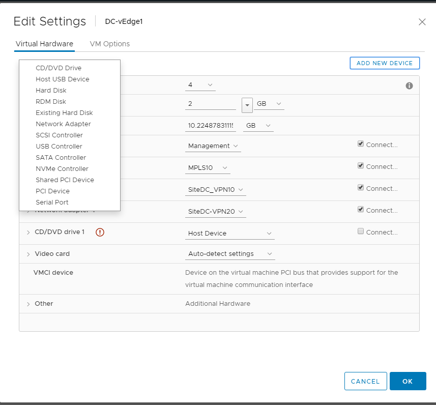
Choose to Add a new device (top right corner) and select Network Adapter to add one (since our deployed VM has only 4 Network Adapters but we will need 5 for our lab)
-
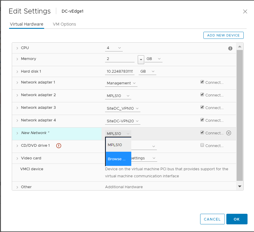
Click on the drop down next to New Network and click on Browse
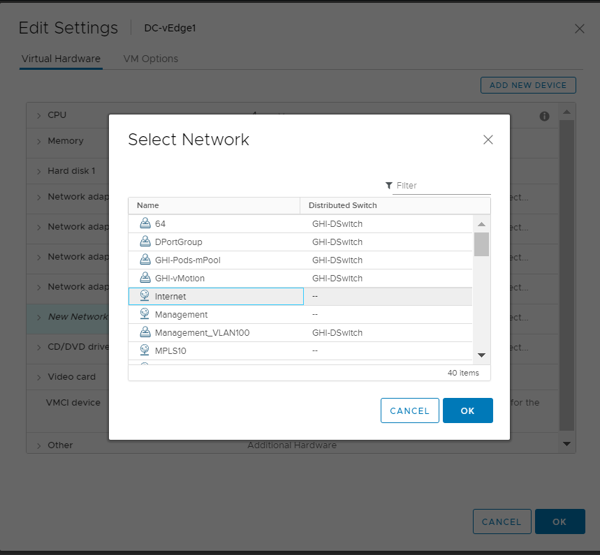
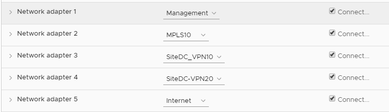
- Choose the Internet Network and click on OK. Make sure the Network Adapters match with the second image below and click on OK again
Warning: The Network Adapter mapping might vary based on the version of vEdge being deployed. Sometimes, trial and error is the easiest way to figure out which Network Adapter maps to which interface on the vEdge
-
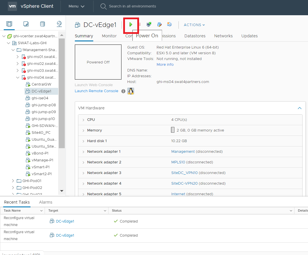
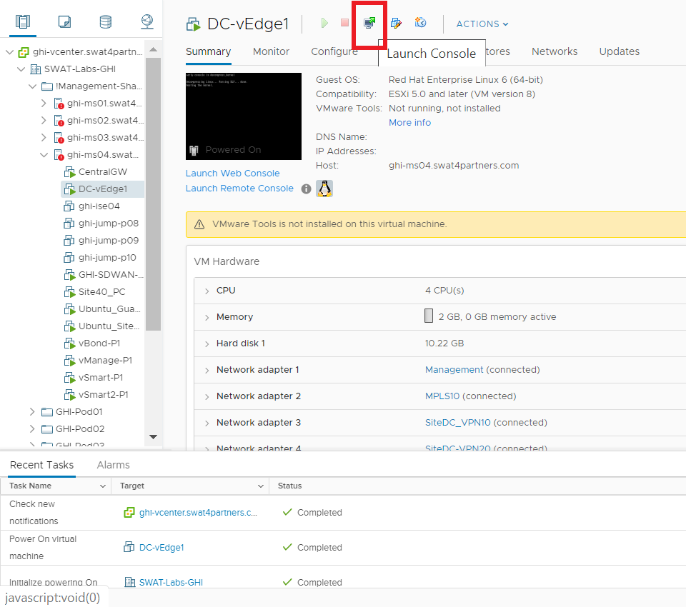
Click on the DC-vEdge1-podX VM and choose to power it on
-
-
-
-
- Onboarding DC-vEdge1
- Bootstrapping DC-vEdge1 (Initial Configuration)
- Installing certificates and activating the vEdge
- Onboarding Verification
- Helpful debugs and logs
Onboarding DC-vEdge1
Bootstrapping DC-vEdge1 (Initial Configuration)
Use the following information in this section (some of the information will be used later)
| SITE ID | SYSTEM IP | VM | Network Adapter | Network | Interface | IP | Gateway |
|---|---|---|---|---|---|---|---|
| 1 | 10.255.255.11 | DC-vEdge1 | Network Adapter 1 | Management | eth0 | 192.168.0.10/24 | 192.168.0.1 |
| Network Adapter 2 | MPLS10 | ge0/1 | 192.0.2.2/30 | 192.0.2.1 | |||
| Network Adapter 3 | SiteDC_VPN10 | ge0/2 | 10.100.10.2/24 | 10.100.10.1 | |||
| Network Adapter 4 | SiteDC-VPN20 | ge0/3 | 10.100.20.2/24 | 10.100.20.1 | |||
| Network Adapter 5 | Internet | ge0/0 | 100.100.100.10/24 | 100.100.100.1 |
-
Console in to the DC-vEdge1 VM from vCenter (you should already be logged in from our last activity)
-
Wait for the VM to prompt you for the username and password and enter the credentials given below. If you get a message stating that they are incorrect, wait for 30 seconds and try again (since the processes need to initialize before you can log in)
Username Password admin admin Note: From version 19.2, the password will need to be reset on initial login. For this lab, we will reset the password toadmin.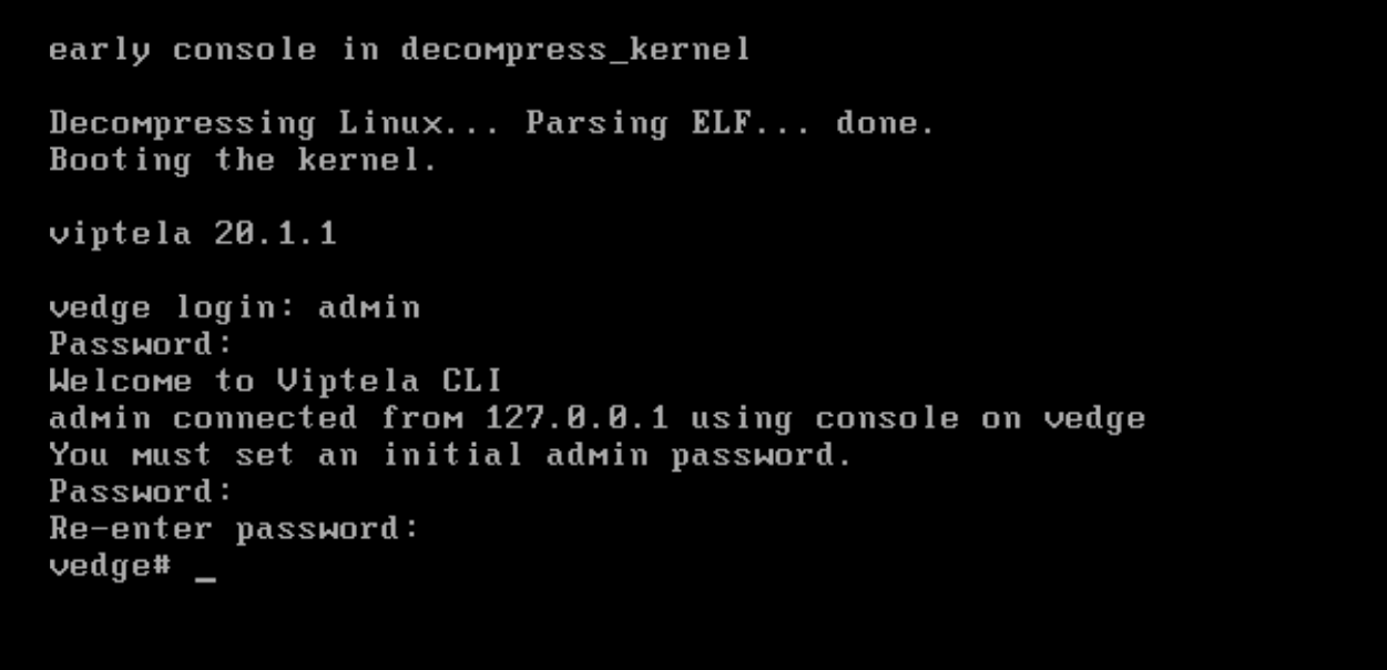
-
Enter the configuration enumerated below. Unfortunately, this will need to be typed out since the console isn’t copy-paste friendly
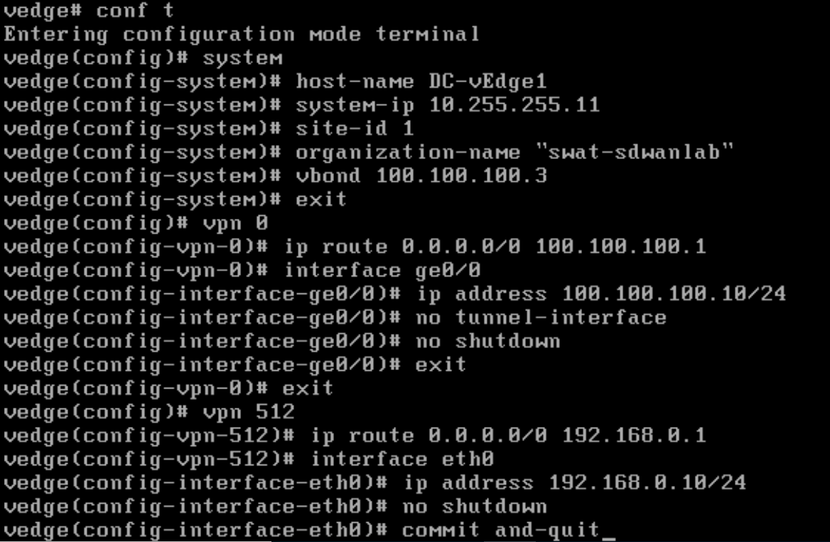
 conf t
 system
  host-name DC-vEdge1
  system-ip 10.255.255.11
  site-id 1
  organization-name "swat-sdwanlab"
  vbond 100.100.100.3
  exit
 !
 vpn 0
  ip route 0.0.0.0/0 100.100.100.1
  interface ge0/0
   ip address 100.100.100.10/24
   no tunnel-interface
   no shutdown
   exit
   !
   exit
 !
 vpn 512
  ip route 0.0.0.0/0 192.168.0.1
  interface eth0
   ip address 192.168.0.10/24
   no shutdown
 !
 commit and-quit
Tip: We are ensuring that the vEdge has basic IP Addressing and Routing to the Controllers.no tunnel-interfacehas been added under the ge0/0 interface in VPN 0 in order to prevent control connections from being established -
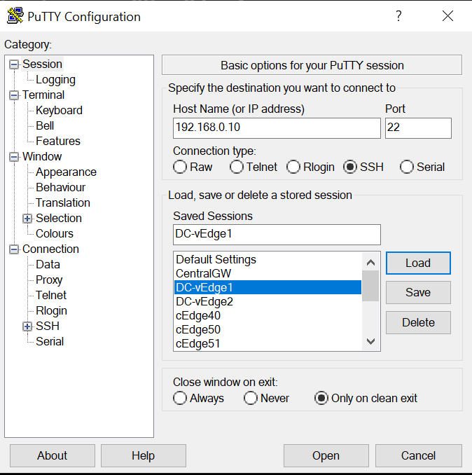
Open Putty and double click the saved session for DC-vEdge1 (or SSH to 192.168.0.10)
-
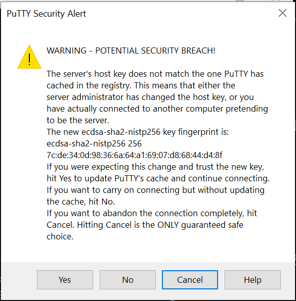
Choose Yes to accept the certificate, if prompted
-
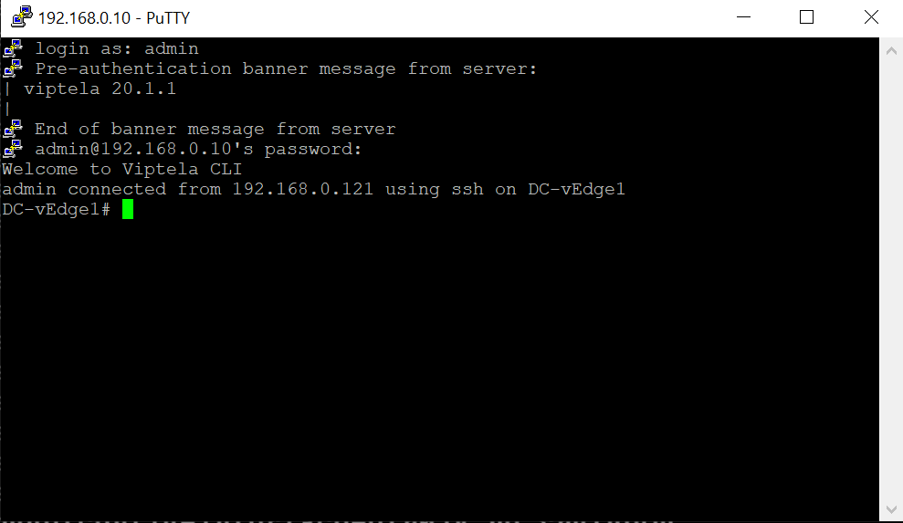
Login using the same credentials as Step 2.
-
-
-
-
- Onboarding DC-vEdge1
-
- Installing certificates and activating the vEdge
- Onboarding Verification
- Helpful debugs and logs
Installing certificates and activating the vEdge
-
Type
vshelland enterscp admin@192.168.0.6:ROOTCA.pem .to copy the ROOTCA.pem certificate to the vEdge. Commands can be copy-pasted now since we have SSH’d in to the vEdge (there is a dot at the end of the scp command). Enteryeswhen prompted and enter the password of vManage (i.e. admin). Exit when done with this step.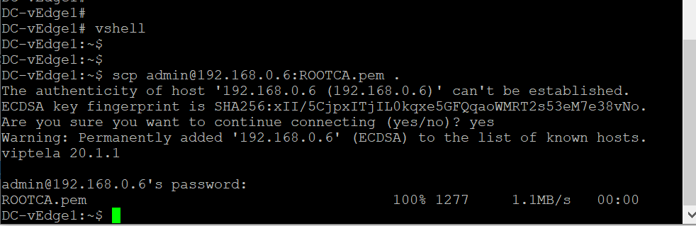
 vshell
 scp admin@192.168.0.6:ROOTCA.pem .
Note: This is NOT how you would normally install certificates over to your devices. In a lab, this manual method works fine but for production environments, the other options are definitely preferred (like Cisco PKI) -
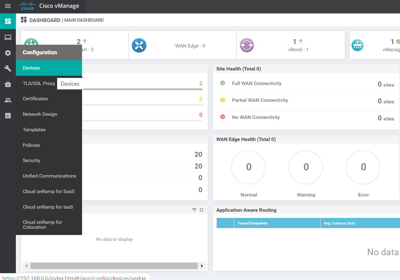
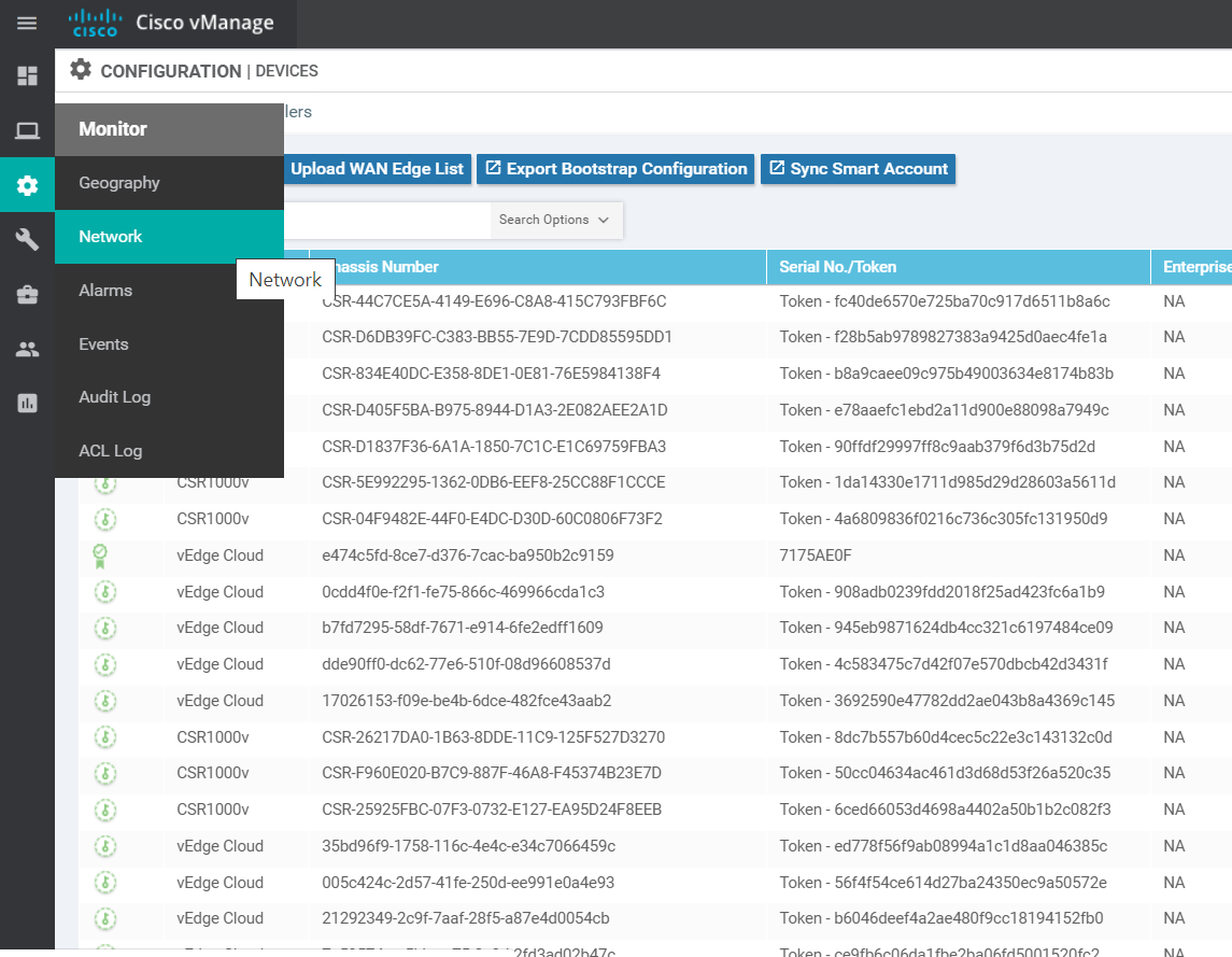
Go to the vManage GUI (https://192.168.0.6) and log in, if logged out. Navigate to Configuration => Devices (from the left-hand side, click on the cog wheel to access the configuration options)
-
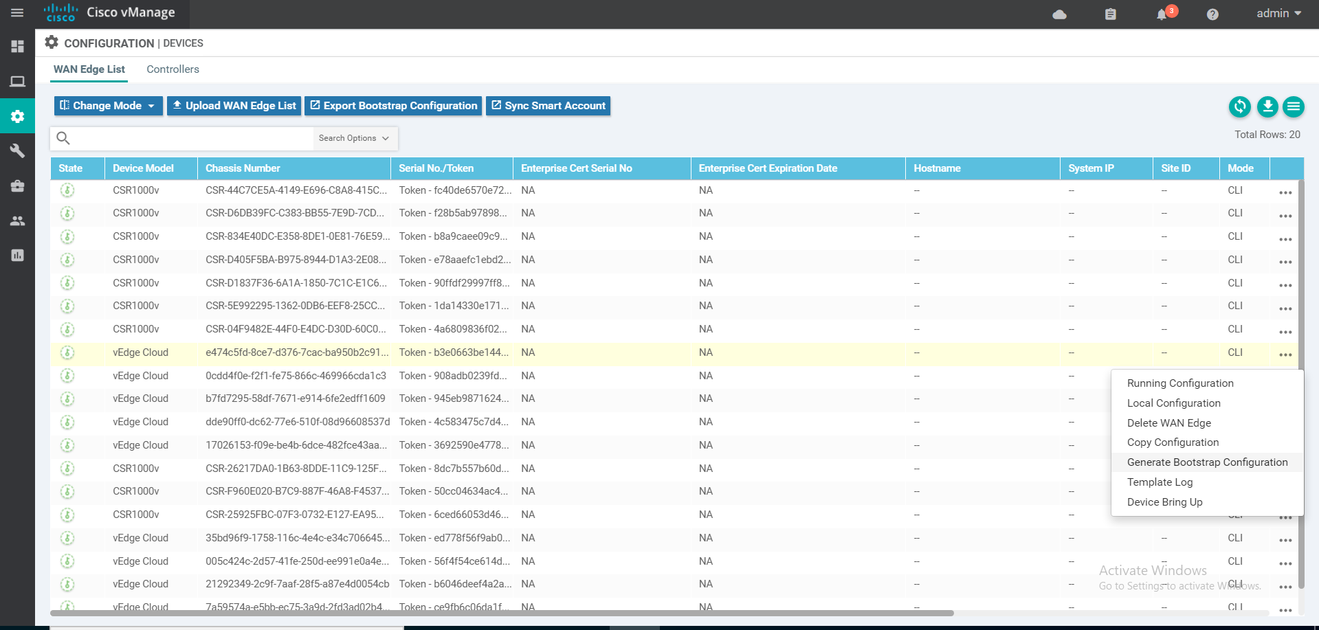
Choose any vEdge Cloud device (it doesn’t matter which one you pick, as long as it is a vEdge Cloud) and click on the three dots at the extreme right-hand side. Choose Generate Bootstrap Configuration
-
Select Cloud-Init and uncheck Include Default Root Certificate. Click on OK
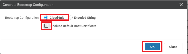
- Make note of the UUID and the OTP values. These will be required to activate the vEdge. It’s best to copy the string and place it in notepad, since we will need to use it in our SSH session to the DC-vEdge1 device. Alternatively, leave this popup open and we can come back to it when required
Important: The UUID and OTP/Token are super important for vEdge Cloud or cEdge CSRs. Physical devices don’t have a token associated with them and are uniquely identified by their serial number
-
Go back to the Putty session for DC-vEdge1 and enter
request root-cert-chain install /home/admin/ROOTCA.pemto install the root cert chain. It should install successfully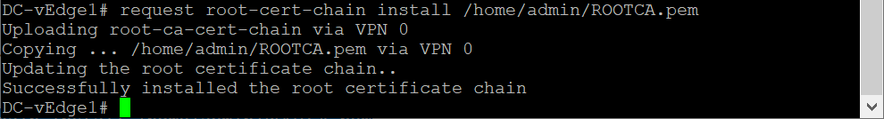
request root-cert-chain install /home/admin/ROOTCA.pem -
Enter
tunnel-interface,encapsulation ipsecandallow-service allunderinterface ge0/0to bring up the tunnel Interface. Make sure tocommit and-quitin order to write the configuration change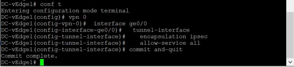
 config t
 vpn 0
 interface ge0/0
  tunnel-interface
  encapsulation ipsec
  allow-service all
  exit
  !
  commit and-quit
This ensures that our vEdge is now able to establish control connections with the vManage and vSmarts via the vBond. However, these connections will not be fully formed till we don’t activate the vEdge itself
-
Issue the
request vedge-cloud activate chassis-number (Enter your UUID) token (Enter the OTP)command. Replace the (Enter your UUID) and (Enter your OTP) fields with the UUID and OTP generated in Step 5 (image below is an example, UUID and OTP may not match).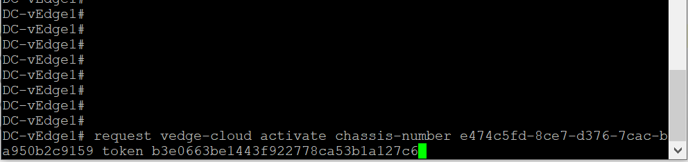
request vedge-cloud activate chassis-number (Enter your UUID) token (Enter the OTP)This completes the Onboarding section for DC-vEdge1
-
-
-
-
-
-
-
- Onboarding Verification
- Helpful debugs and logs
Onboarding Verification
-
Wait for a couple of minutes and run
show control connectionsin the DC-vEdge1 CLI. We should see that the vEdge has been able to establish a DTLS tunnel with the vManage and the vSmarts. If you don’t see any output, wait for a couple of minutes and run the command again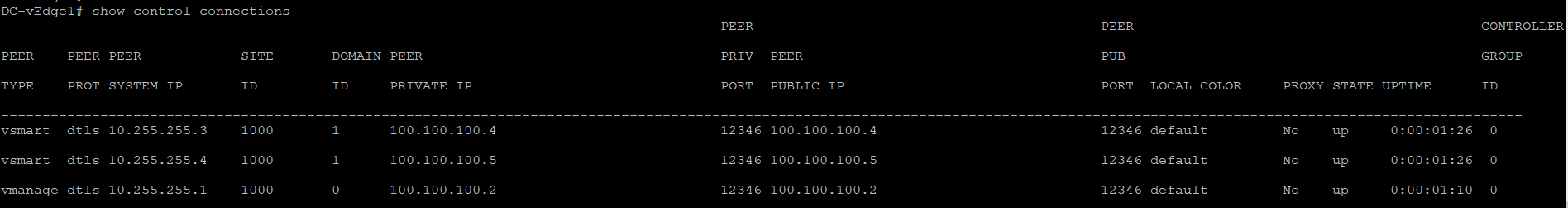
show control connectionsTip: You can also issueshow control connections-historyin the event of failures to find out why is the connection not working as expected. A few helpful commands areshow certificate installed,show certificate root-ca-cert,show control local-propertiesandshow certificate validity. Most of these commands give us details about the status of certificates on the device and are helpful in ascertaining the root cause of failure when control connections aren’t getting established. -
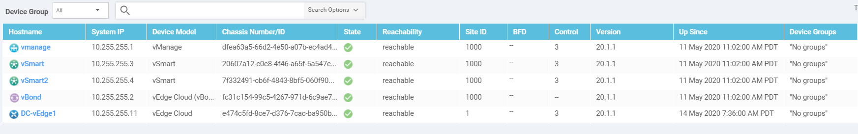
On the vManage GUI, navigate to Monitor => Network Devices (the computer icon on the left-hand side)
-
DC-vEdge1 should show up in the list of devices
-
Click on DC-vEdge1 and navigate to Troubleshooting => Control Connections(Live view). You should see the vEdge successfully connected to 2 vSmarts and 1 vManage
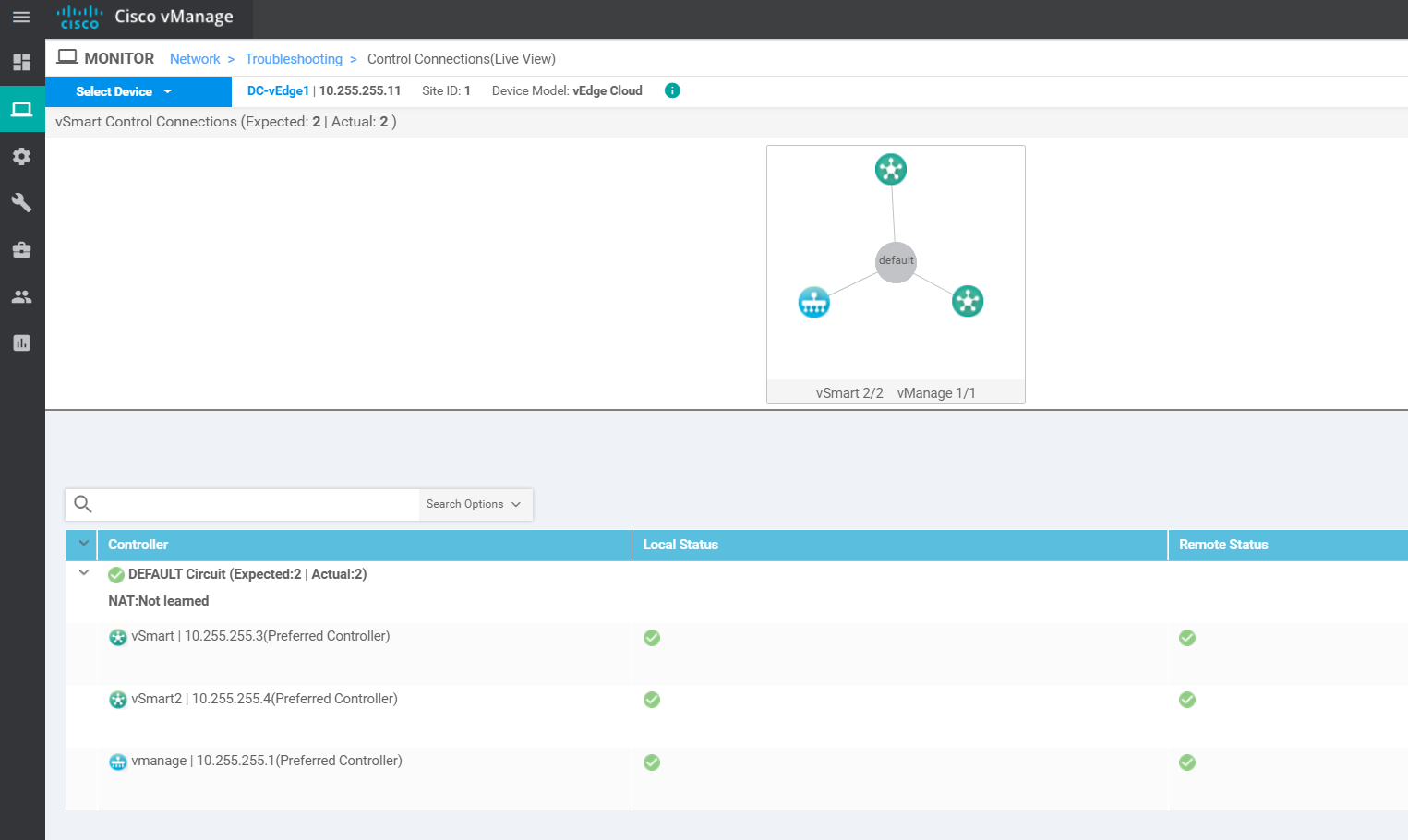
This completes the verification activity.
-
-
-
-
-
-
-
-
- Helpful debugs and logs
Helpful debugs and logs
-
On the CLI for DC-vEdge1, issue
debug vdaemon allfollowed byclear control connections. This will tear down all the control connections and the vEdge will rebuilt the DTLS tunnels. We can capture the logs to see the process associated with the DTLS tunnels being built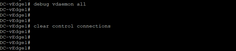
debug vdaemon all clear control connections -
Wait for a couple of minutes and go to
vshell. Typecat /var/log/tmplog/vdebugto view the contents of the log file
-
Given below are a couple of sample outputs
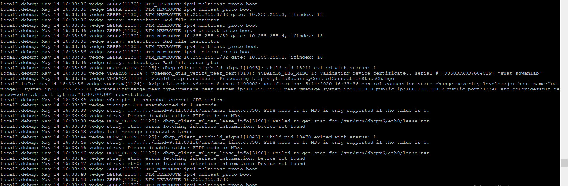
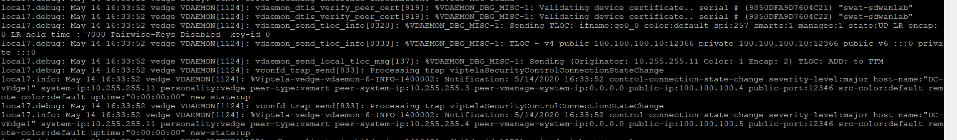
Use
no debug vdaemon allto disable the debug
This completes our onboarding activity for DC-vEdge1.