- Create a Localized Policy
- Add a Class List and a QoS Map
- Configure the IPv4 ACL Policy
- Complete and apply the localized policy
- Apply the ACL and QoS Map
- Activity Verification
While Application Aware Routing allows us to choose the path taken by traffic and switch paths based on SLA parameters, QoS strategies in SD-WAN allow packets to be marked with standard DSCP values which are then utilized to prioritize packets accordingly.
Let’s assume that our Corporate VPN (VPN 10) has, among other traffic, VoIP packets flowing through it. We would want to follow some QoS strategy to ensure that these VoIP (RTP, Video and Signalling) packets are placed in a Low Latency Queue, with corresponding strategies for other types of traffic.
Create a Localized Policy
QoS in the SD-WAN world is implemented via Localized Policies. Differences in Localized and Centralized Policies can be found over here.
Add a Class List and a QoS Map
-
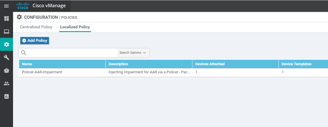
On the vManage GUI, click on Configuration => Policies and choose the Localized Policy tab. Click on Add Policy
-
Under Create Groups of Interest click on Class Map on the left-hand side. Click on New Class List and specify the Class as Voice. The Queue should be 0. Click on Save
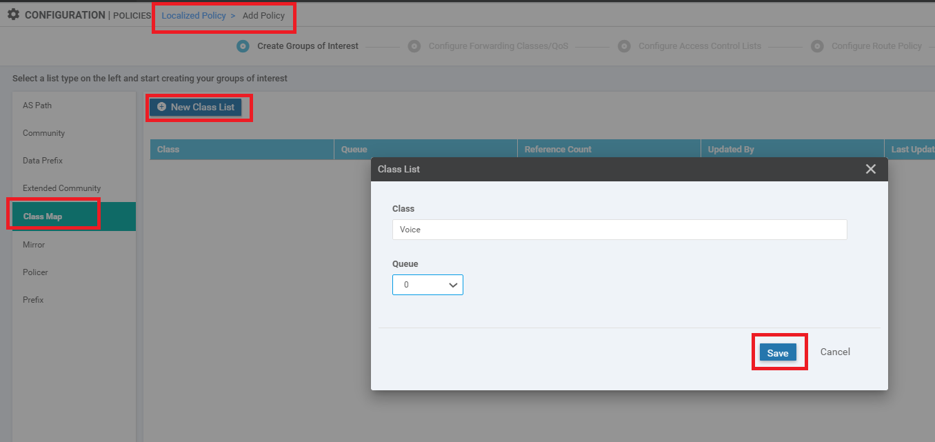
This creates our Class List for VoIP traffic and puts the traffic in Queue 0.
-
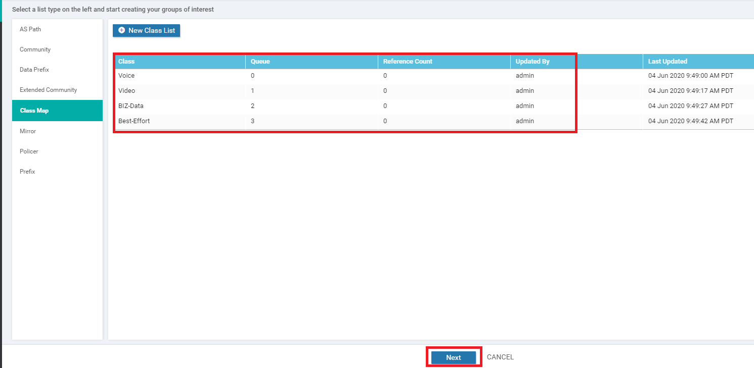
Click on New Class List and create 3 more Class Lists, as shown below. Remember to hit Save after each Class List is created
Class Queue Video 1 BIZ-Data 2 Best-Effort 3 Once all the Class Lists are created, click on Next
-
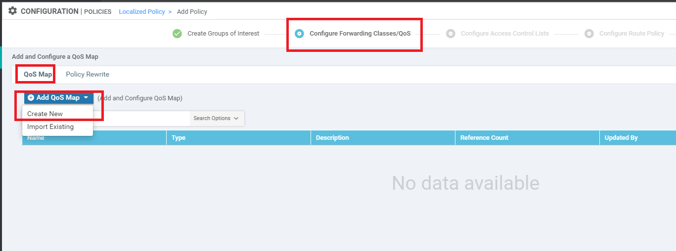
The Class Lists are referenced in QoS Maps. Under Configure Forwarding Classes/QoS, make sure you’re on the QoS Map tab and click on Add QoS Map
-
Give the QoS Map a Name of WAN-QoS and a Description of WAN QoS. Click on Add Queue. Specify the following details and click on Save Queue
Queue Bandwidth % Buffer % Scheduling Drops Forwarding Class 1 30 30 Wighted Round Robin (WRR) Tail Video (Auto Populated) 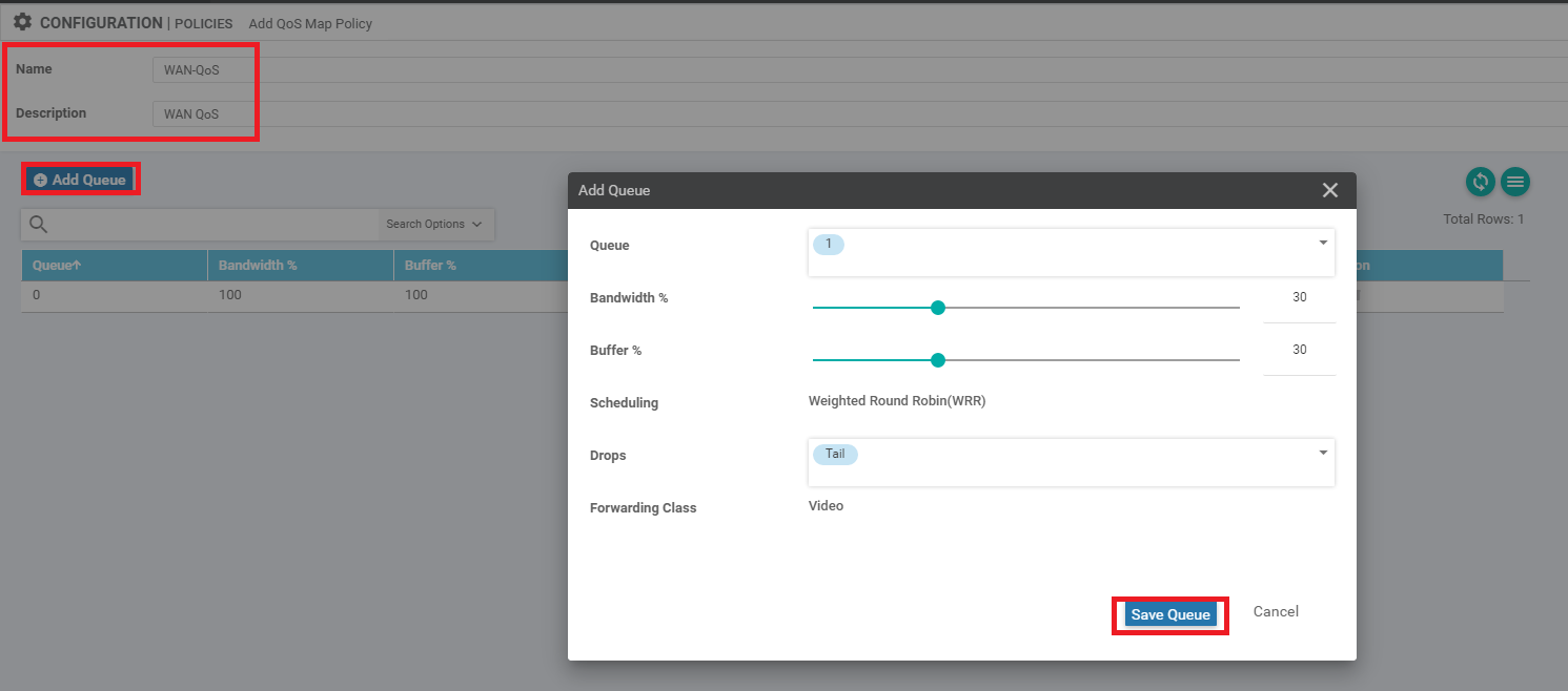
-
Click on Add Queue and add a couple more queues as per the table given below. Remember to click on Save Queue after you’re done setting up the Queue
Queue Bandwidth % Buffer % Scheduling Drops Forwarding Class 2 40 40 Weighted Round Robin (WRR) Random Early BIZ-Data (Auto Populated) 3 10 10 Weighted Round Robin (WRR) Random Early Best-Effort (Auto Populated) 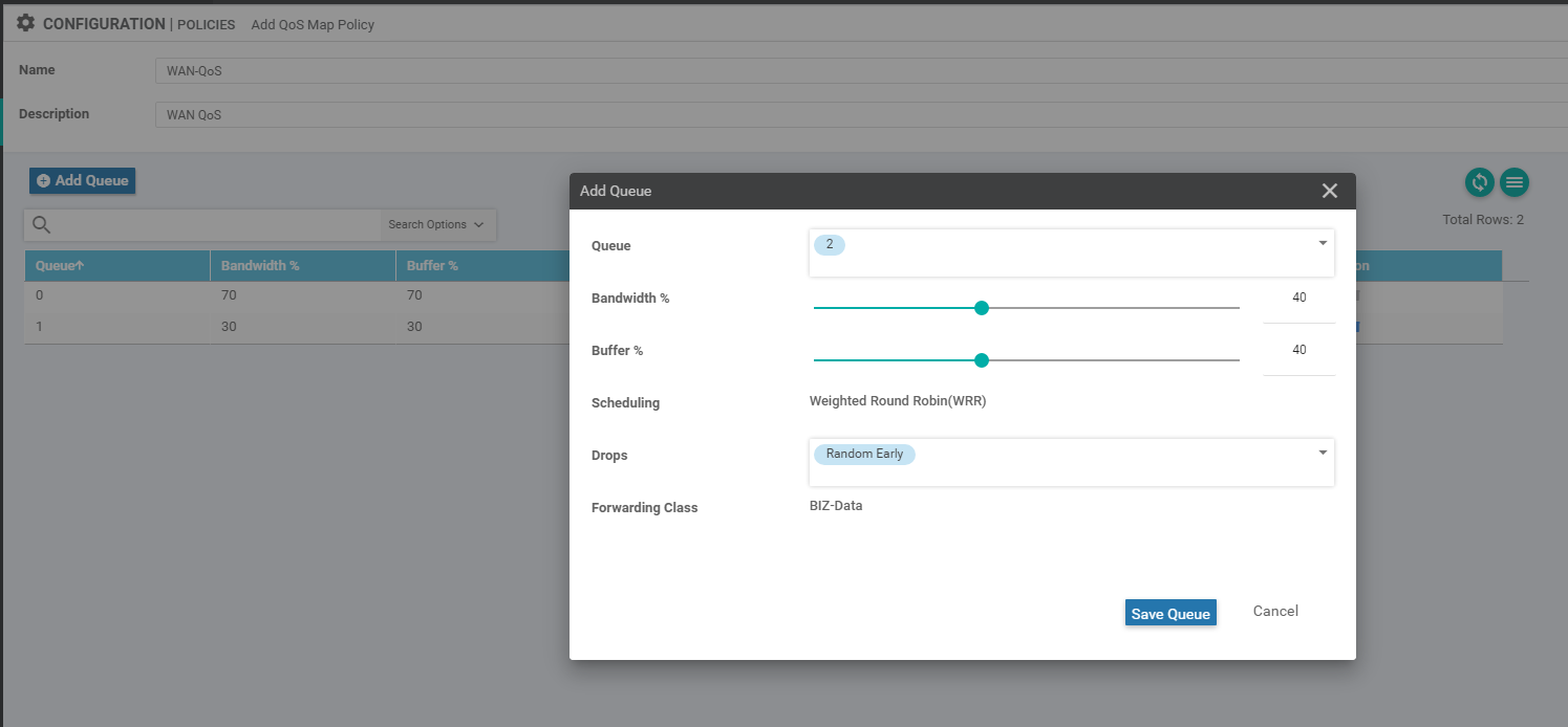
Queue 2 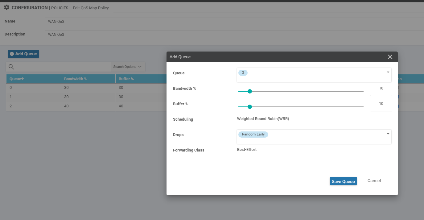
Queue 3 -
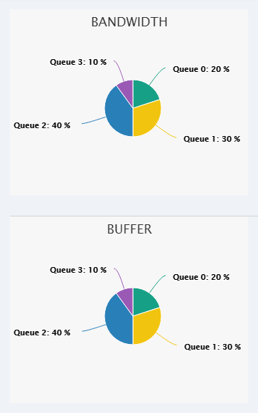
The wagon wheel that shows Queue Bandwidth and Buffer allocation should change to reflect the settings in the Queues that were just created
-
The QoS Map queues should look like the image below. Click on Save Policy to save your QoS Map and then click on Next
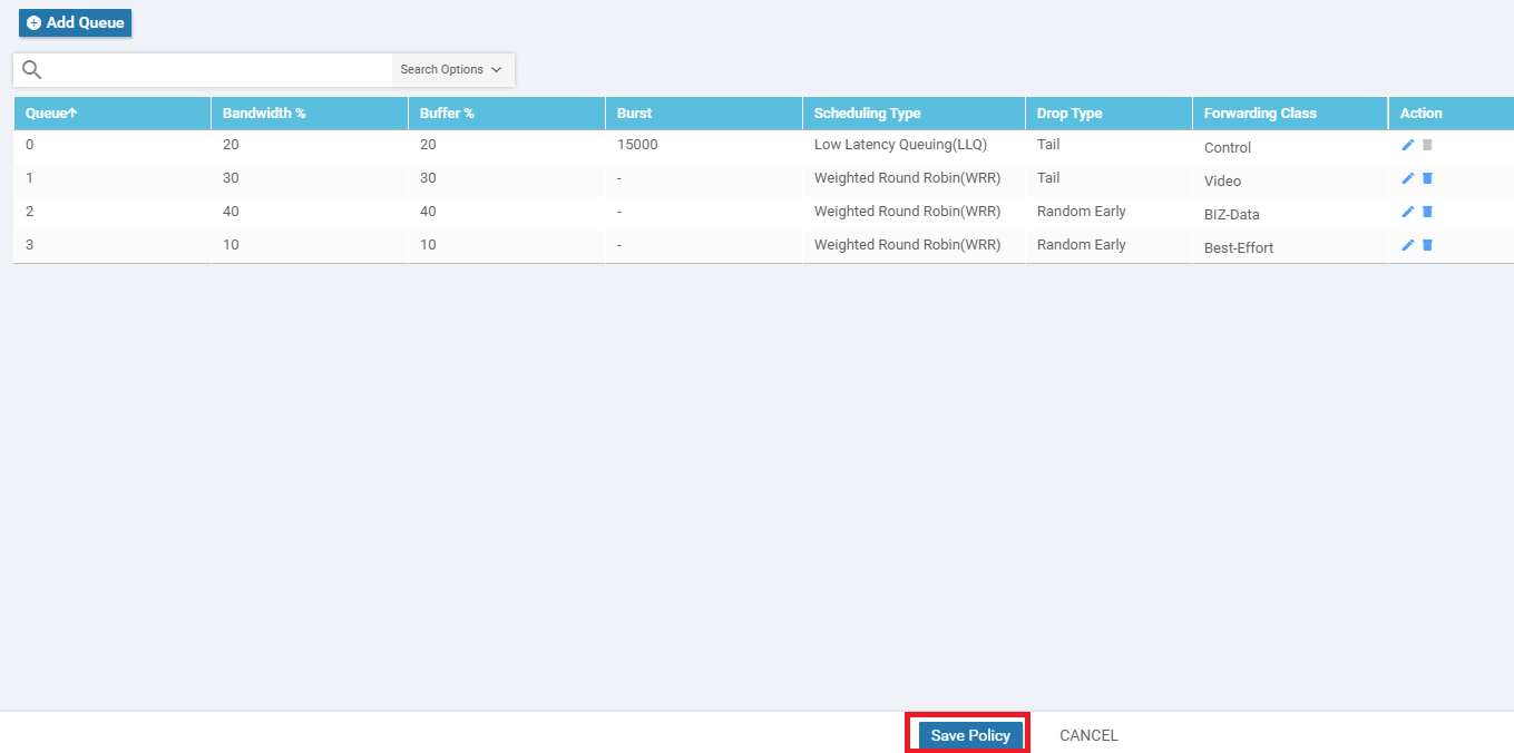
Notice that the Queue 0 Forwarding Class is populated as Control. Control network traffic (not related to VoIP) is also included in Queue 0 by default. Any traffic that’s mapped to Queue 0 is regarded as LLQ traffic.
This completes the QoS Map configuration. We will continue with building our Main Policy in the next section.
- Create a Localized Policy
-
- Configure the IPv4 ACL Policy
- Complete and apply the localized policy
- Apply the ACL and QoS Map
- Activity Verification
Configure the IPv4 ACL Policy
-
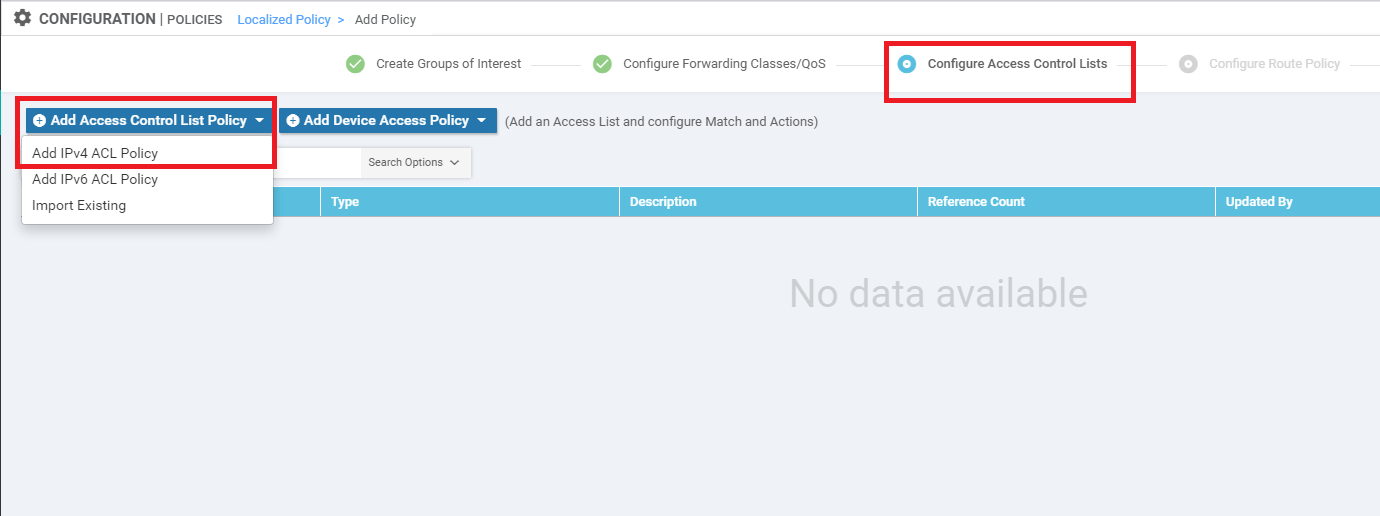
Continuing from the QoS Map which we just built, you show now be at the Configure Access Control Lists page. An ACL Policy can be used for classification of traffic on the LAN. Click on Add Access Control List Policy and choose to Add IPv4 ACL Policy
-
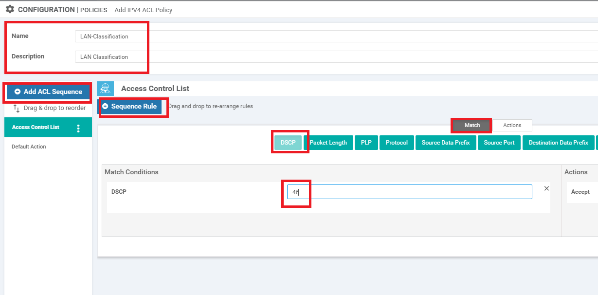
Give the ACL Policy a Name of LAN-Classification and a Description of LAN Classification. Click on Add ACL Sequence and then click on Sequence Rule. Make sure you’re on the Match tab and click on DSCP. Enter a DSCP value of 46. This specifies our match criteria
-
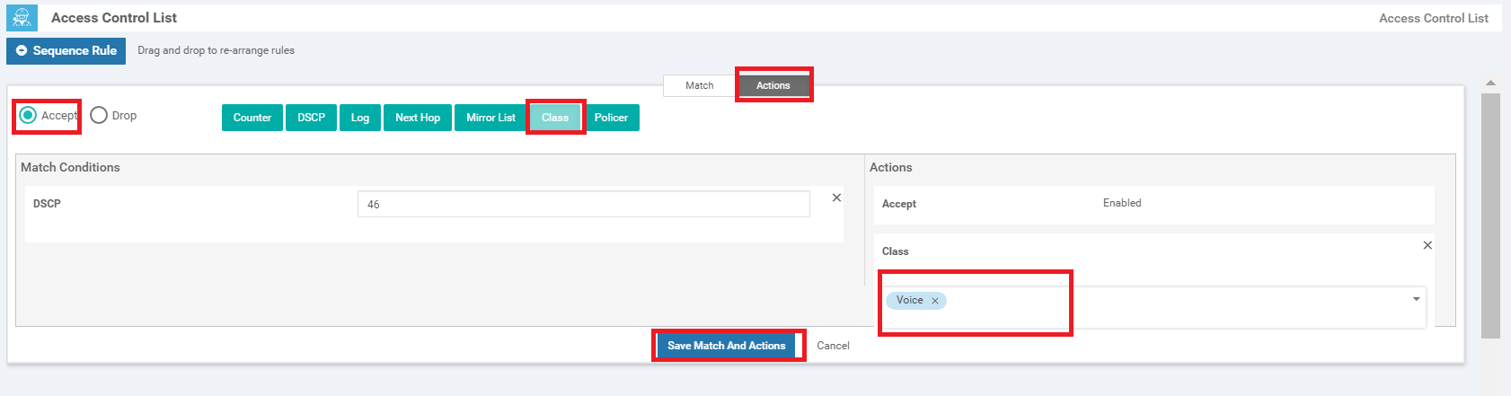
Click on the Actions tab and make sure the Accept radio button is selected. Click on Class and select the Voice Class List which we created before. Click on Save Match and Actions
-
Click on Sequence Rule and follow the same procedure to create rules as per the following table. Use the images below the table for reference (the actions tab should always have the Accept radio button selected). Make sure that you click on Save Match and Actions once done creating each rule
DSCP Class 34 Video 26 BIZ-Data Leave Blank Best-Effort 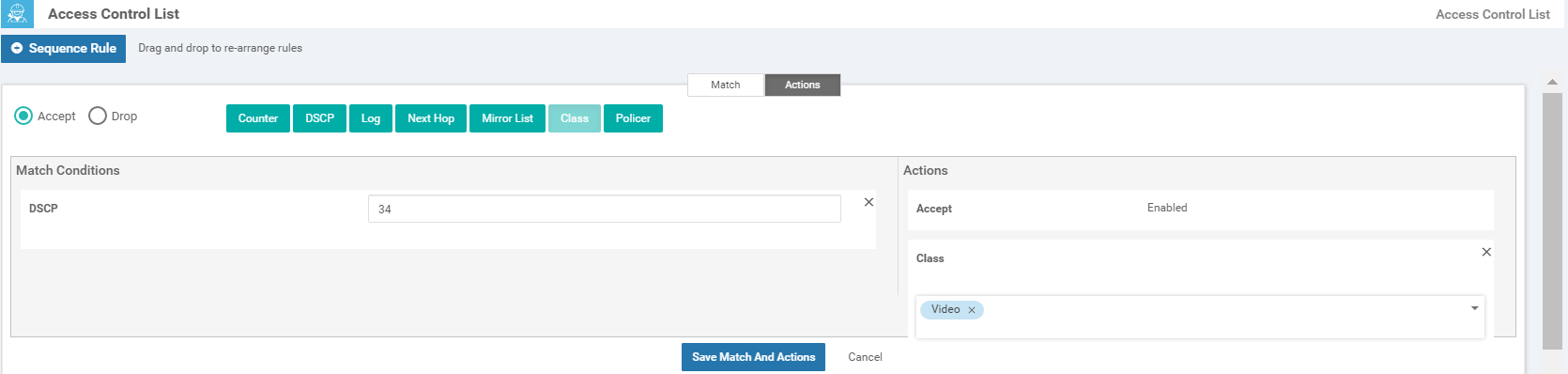
Sequence Rule for Video 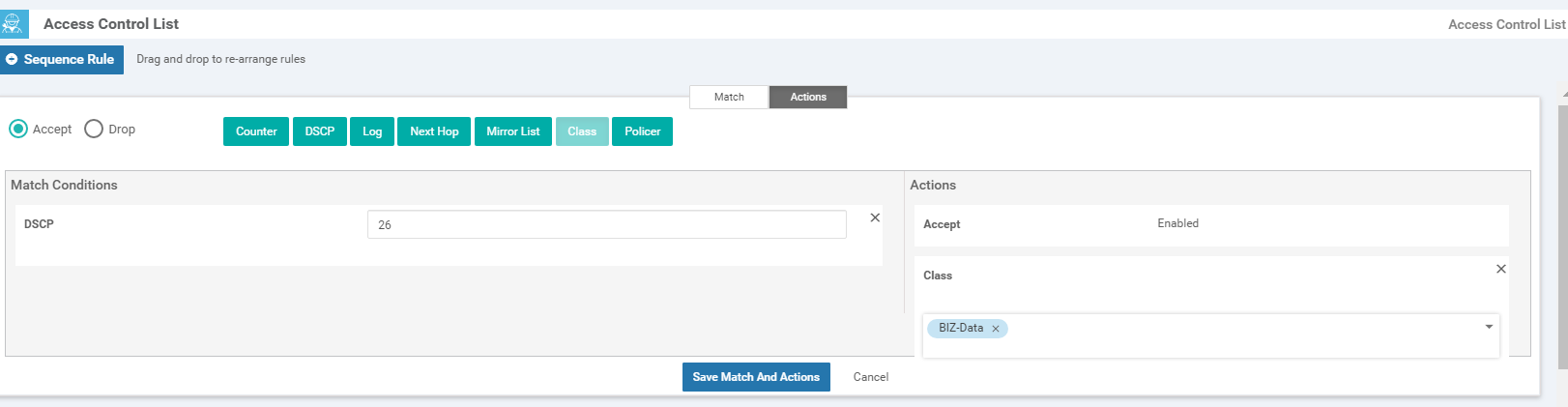
Sequence Rule for BIZ-Data 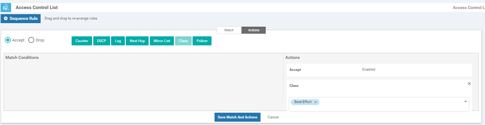
Sequence Rule for Best-Effort -
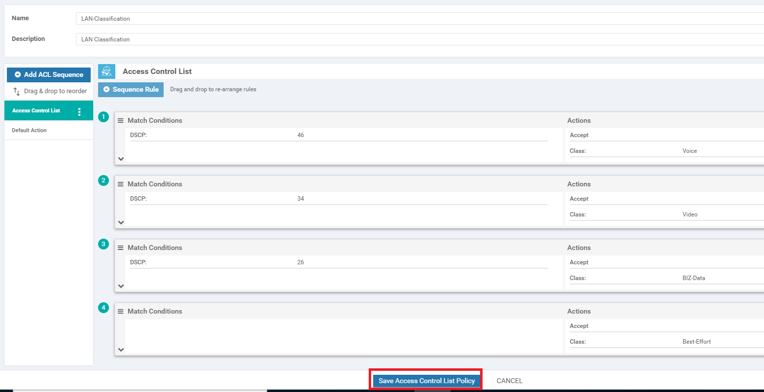
Verify that the Access Control List Policy looks like the image below (i.e. you should see 4 sequence rules, one for each Class List with the corresponding DSCP values as match conditions) and click on Save Access Control List Policy
-
Click on Next twice and you should be at the Policy Overview page, which continues in the next section.
- Create a Localized Policy
-
-
- Complete and apply the localized policy
- Apply the ACL and QoS Map
- Activity Verification
Complete and apply the localized policy
-
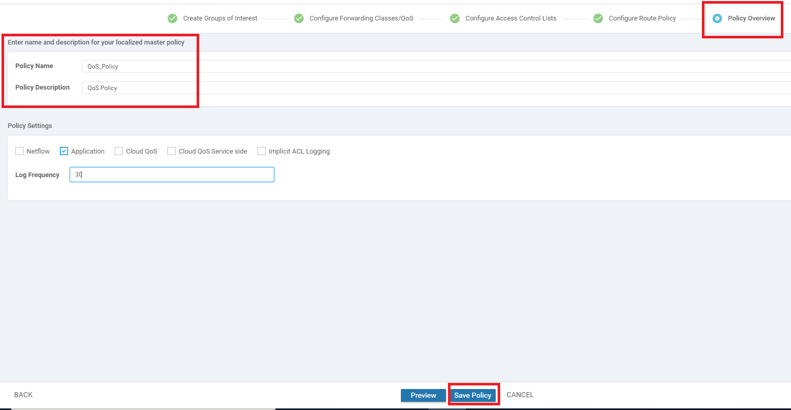
Continuing from the previous section, while on the Policy Overview page, give your policy a Name of QoS_Policy and a Description of QoS Policy. Under Policy Settings, put a check mark next to Application and set the Log Frequency to 30 (this will come into play if you are going through the SD-AVC configuration section). Click on Save Policy
-
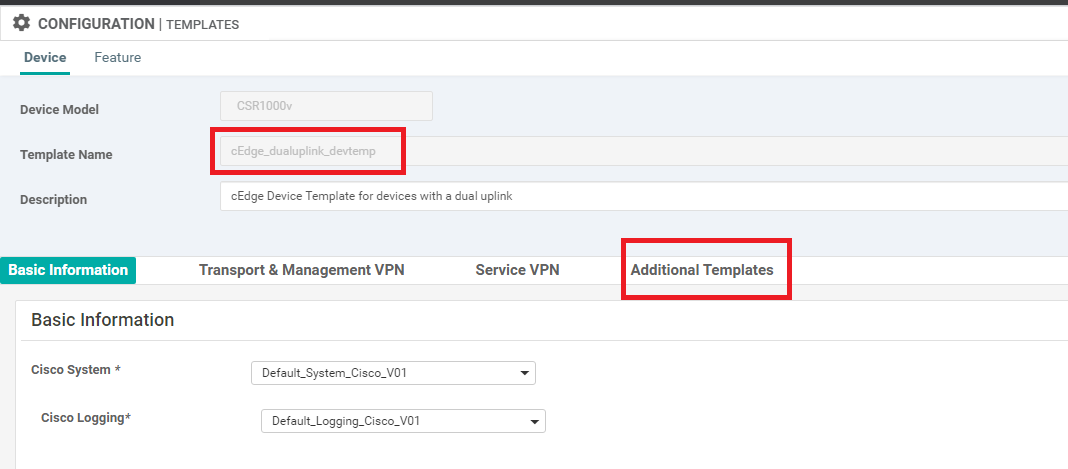
Navigate to Configuration => Templates and locate the cedge_dualuplink_devtemp Device Template. Click on the three dots next to it and choose to Edit. Click on Additional Templates
-
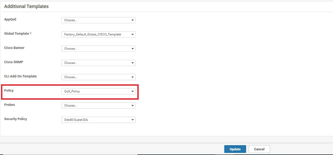
Populate QoS_Policy in the Policy drop down. If you have gone through the Guest DIA configuration, note that this will break Guest DIA functionality. In the real world, the QoS Policy we configured should be included within the same policy. Click on Update
-
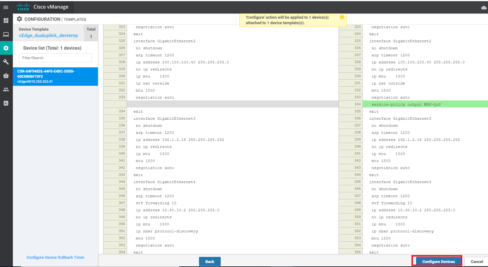
Click on Next and then Configure Devices. You can view the side by side configuration, if you want to
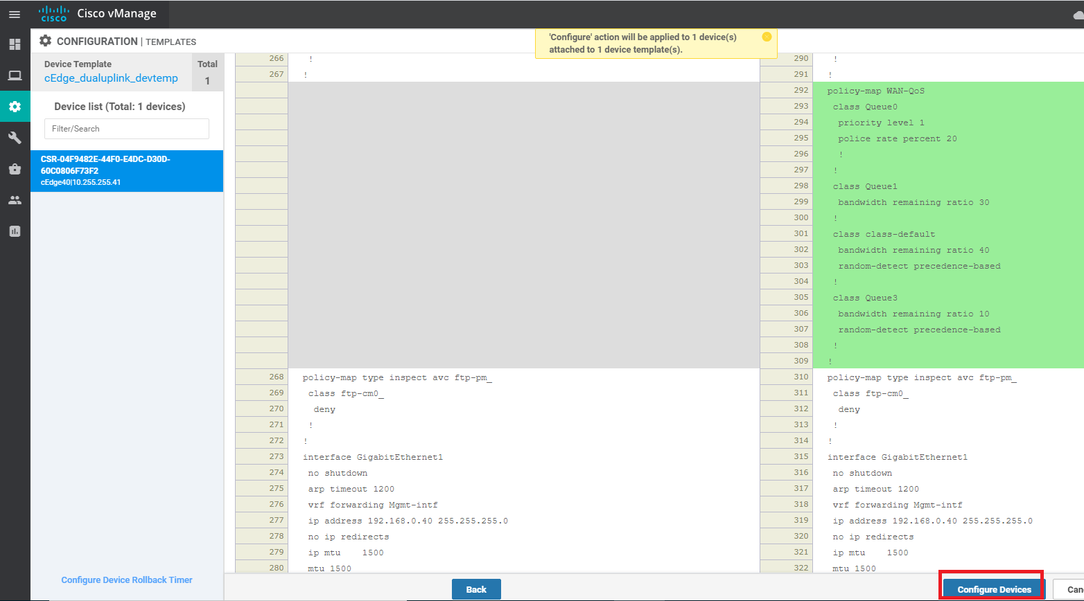
We have completed application of the QoS Policy for our Device. This will create the QoS Maps and inject the corresponding Queues in the Scheduler.
-
-
-
-
- Apply the ACL and QoS Map
- Activity Verification
Apply the ACL and QoS Map
We have created the QoS strategy for our network, the only thing that’s left is to apply and test our QoS configuration.
To apply the configuration, we will be modifying the Service VPN 10 interface such that traffic is classified on the basis of the ACL we created, in the inbound direction.
The QoS Map will be applied in the outbound direction on the WAN interfaces (INET and MPLS)
-
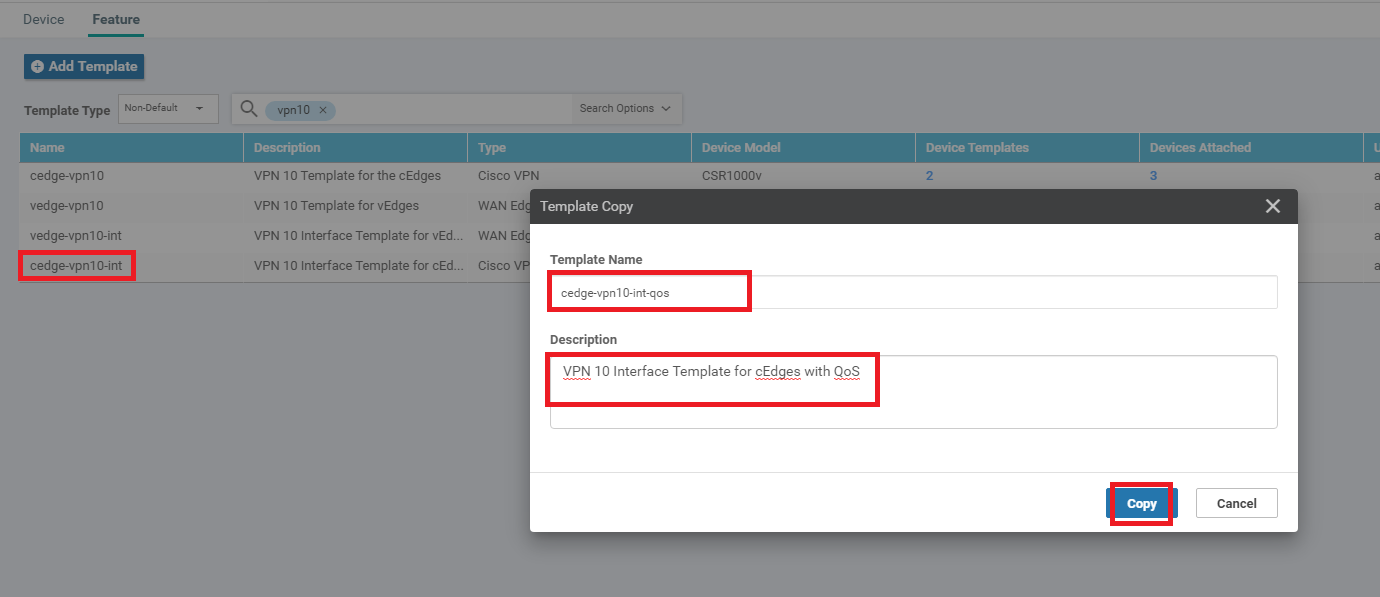
Navigate to Configuration => Templates => Feature Tab and locate the cedge-vpn10-int Feature Template. Click on the three dots next to it and choose to Copy the Template. Give a name of cedge-vpn10-int-qos to the copied template with a Description of VPN 10 Interface Template for cEdges with QoS and click on Copy
-
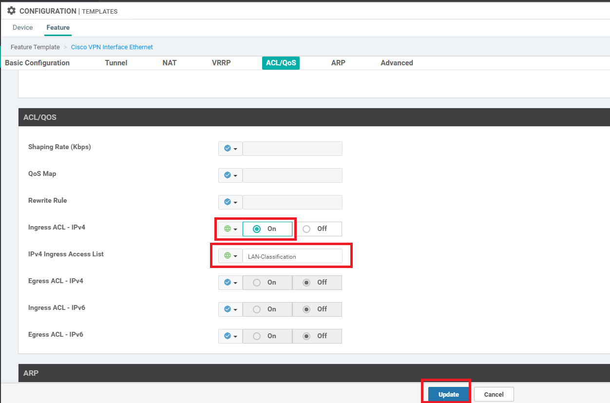
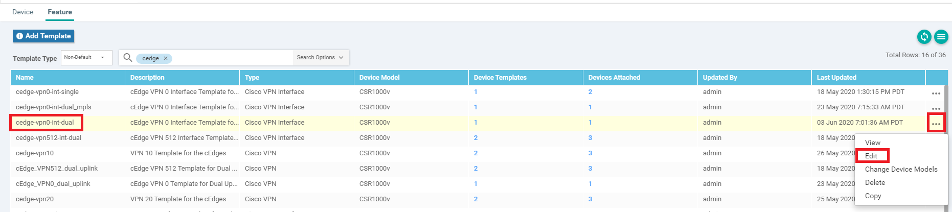
Locate the newly copied cedge-vpn10-int-qos Feature Template and click on the three dots next to it. Choose to Edit the template. Make sure the Description is updated and scroll down to the ACL/QoS section. Set Ingress ACL - IPv4 to a Global value of On and enter LAN-Classification as the IPv4 Ingress Access List. This needs to match with the ACL we created (case sensitive). Click on Update
-
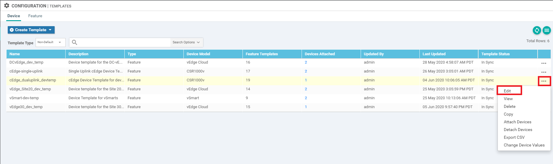
Navigate to the Device tab in Configuration => Templates and locate the cedge_dualuplink_devtemp. Click on the three dots next to it and choose Edit
-
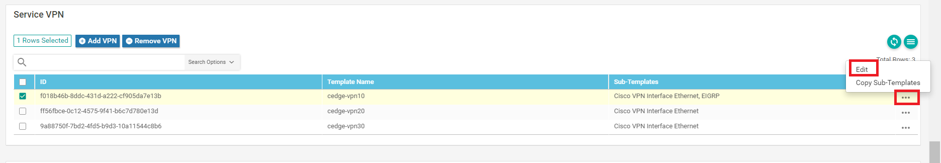
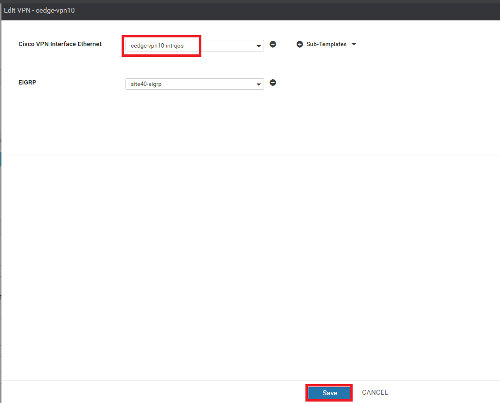
In the Service VPN section, click on the three dots next to the cedge-vpn10 Template and choose Edit
-
Change the template under Cisco VPN Interface Ethernet to cedge-vpn10-int-qos and click on Save
-
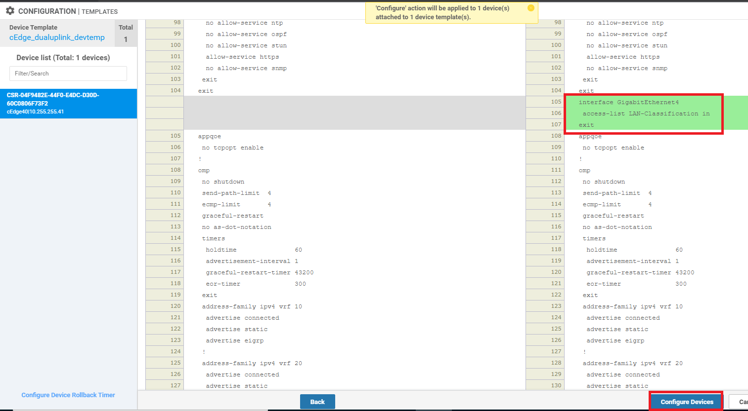
Click on Next and choose to Configure Devices. The side-by-side configuration can be viewed and we should see the LAN-Classification ACL being applied on GigabitEthernet4 (Service VPN Interface for VPN 10) in the incoming direction
-
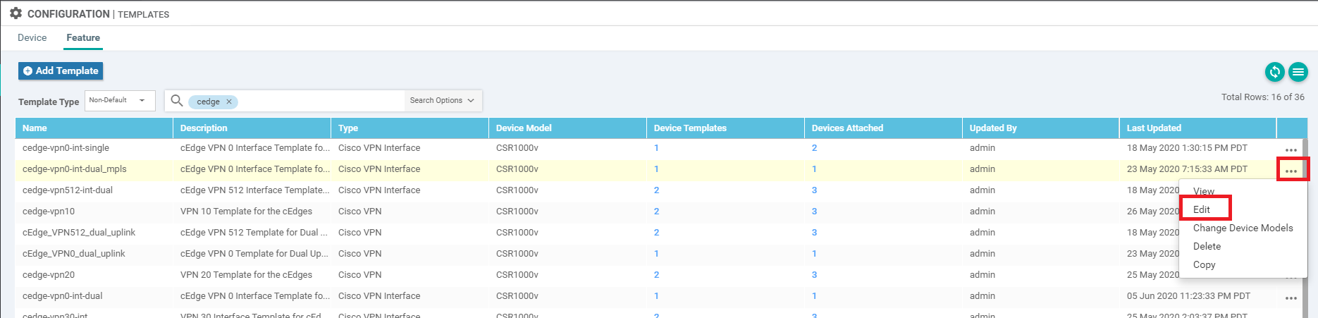
Head back over to Configuration => Template => Feature Tab and locate the cedge-vpn0-int-dual template. Click on the three dots next to it and click Edit. We will be updating the VPN 0 Internet interface with the QoS Map we created before
-
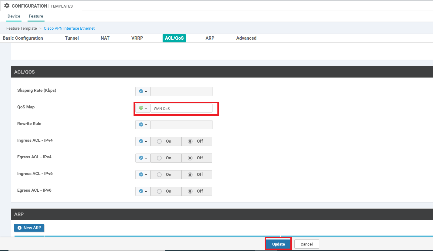
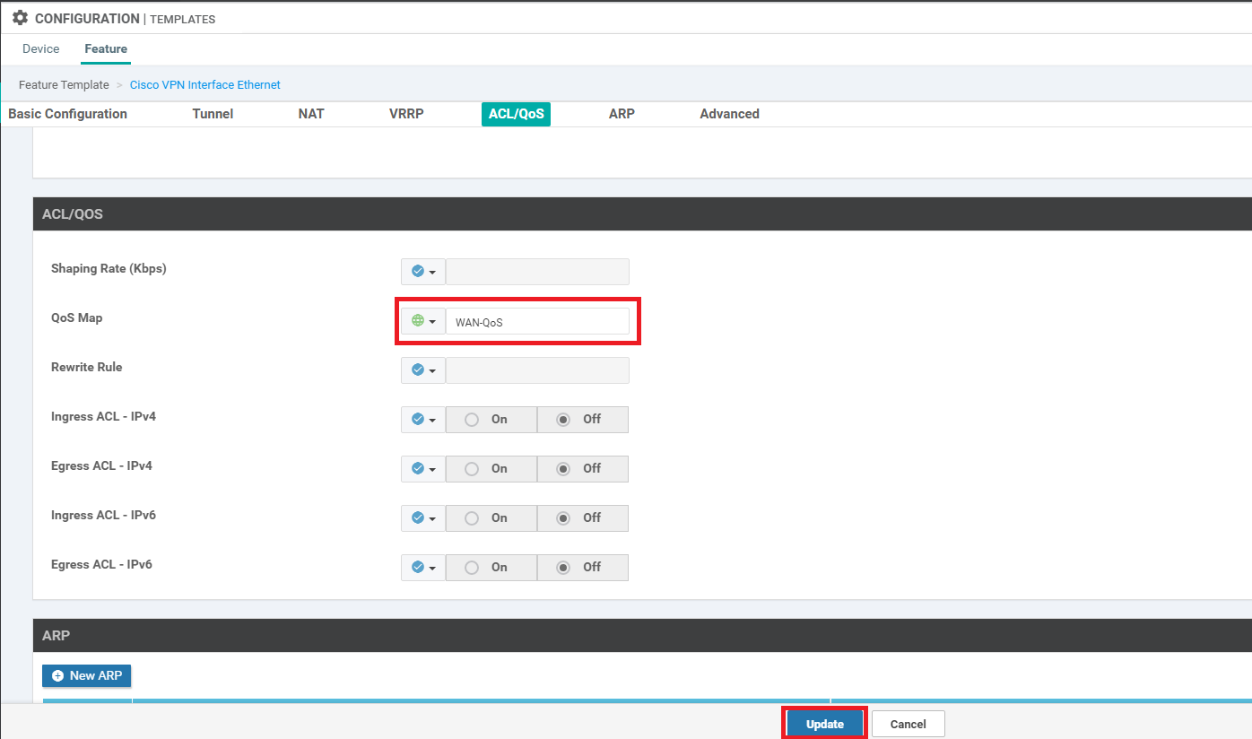
Under the ACL/QOS section, specify the QoS Map as a Global value and enter WAN-QoS (case sensitive, should match with the QOS Map we created before). Click on Update
-
Click on Next and then Configure Devices. If you want, inspect the side-by-side configuration before clicking on Configure Devices and you will notice that the WAN-QoS Policy will be applied to GigabitEthernet2 (WAN VPN 0 Interface for INET)
-
Under the Configuration => Template => Feature Tab locate the cedge-vpn0-int-dual_mpls template. Click on the three dots next to it and click Edit. We will be updating the VPN 0 MPLS interface with the QoS Map we created before
-
Under the ACL/QOS section, specify the QoS Map as a Global value and enter WAN-QoS (case sensitive, should match with the QOS Map we created before). Click on Update
-
Click on Next and then Configure Devices. If you want, inspect the side-by-side configuration before clicking on Configure Devices and you will notice that the WAN-QoS Policy will be applied to GigabitEthernet3 (WAN VPN 0 Interface for MPLS). Check the configuration pushed by logging in to the CLI for cEdge40 via Putty and issuing
show running | sec interface Gig. We should see the WAN_QoS policy applied under GigabitEthernet2 and GigabitEthernet3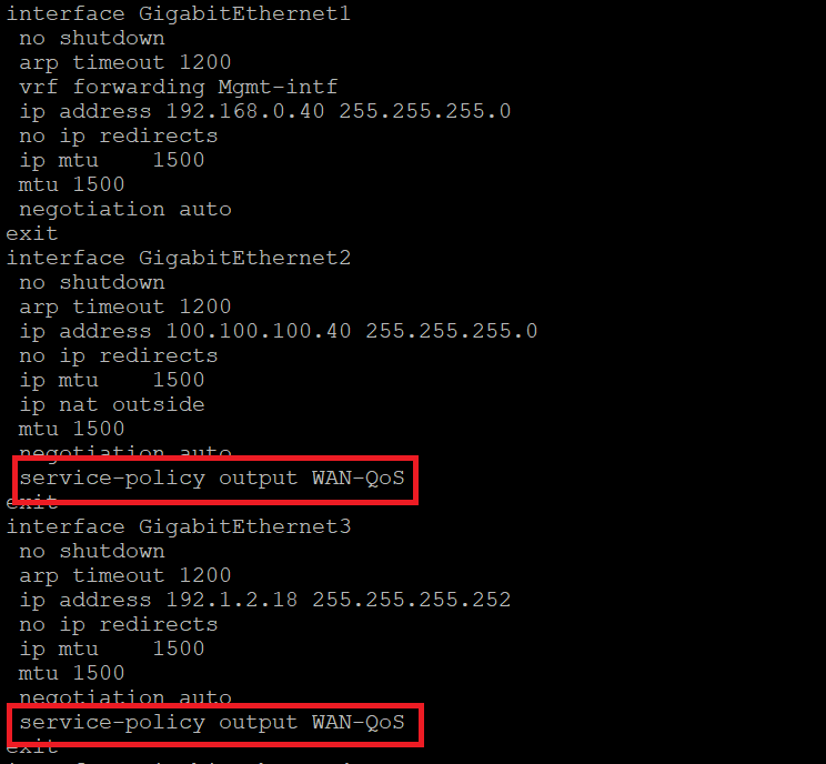
This completes the configuration of our QoS Policy in VPN 10 at Site 40.
-
-
-
-
-
- Activity Verification
Activity Verification
-
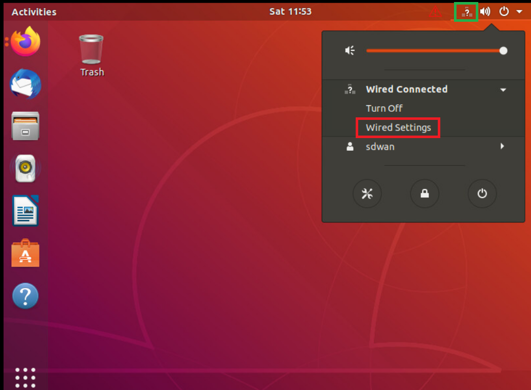
Log in to vCenter (use the bookmark or go to 10.2.1.50/ui if connected to the GHI DC and 10.1.1.50/ui if connected to the SJC DC) using the credentials provided to you. Locate the sdwan-sjc/ghi-site40pc-podX VM and click on it. Open the Web Console to the Site 40 PC VM and log in. The Username is sdwan and the password is C1sco12345. Click the network icon in the top-right corner and go to Wired Settings
-
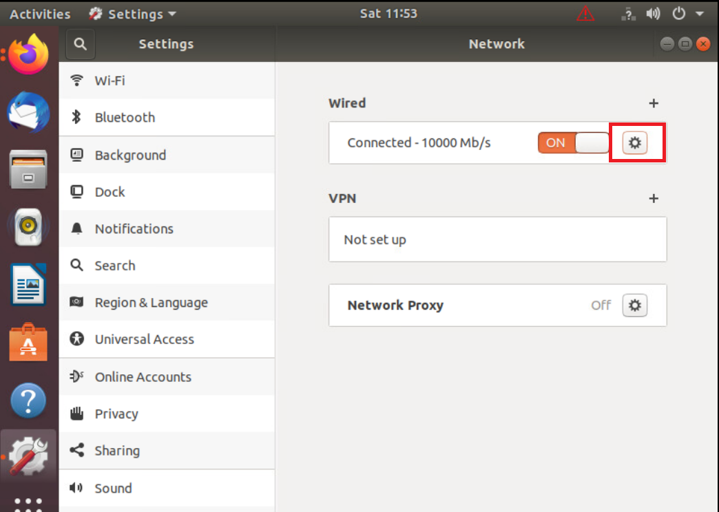
Click on the cog wheel/gear icon
-
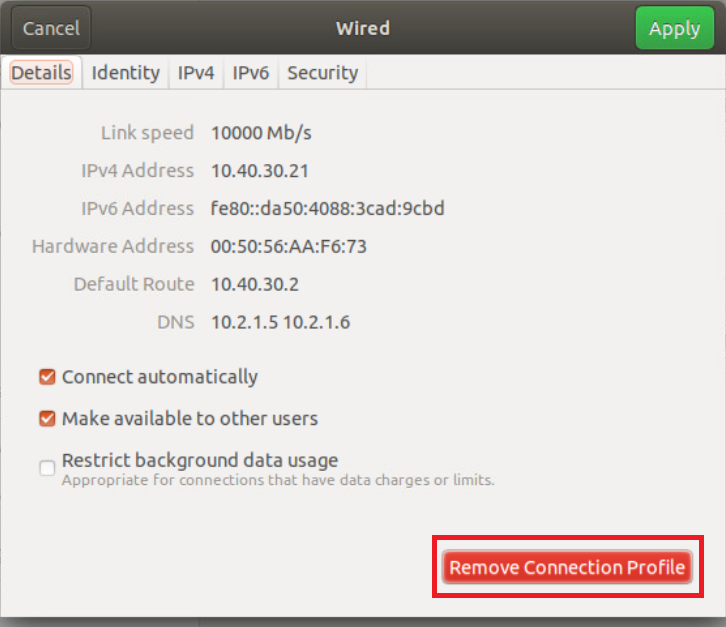
Click on Remove Connection Profile
-
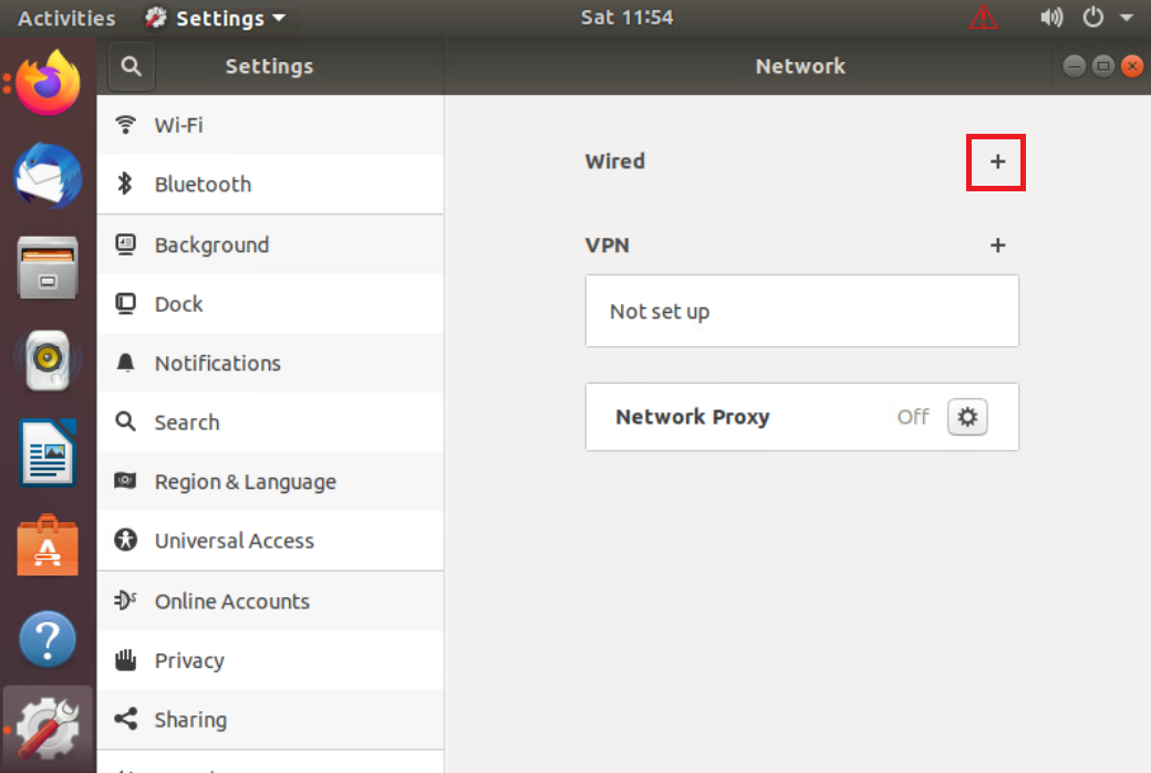
The + sign should show up next to Wired. If you still see a cog wheel/gear icon, click on it and choose Remove Connection Profile again. Once the + icon is visible, click on it
-
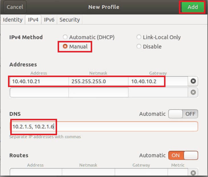
Go to the IPv4 tab and set the IPv4 Method as Manual. Enter the following details and click on Add
Address Netmask Gateway DNS 10.40.10.21 255.255.255.0 10.40.10.2 Automatic - Off
10.y.1.5, 10.y.1.6Over here, y is 1 if you’re on the SJC DC and 2 if you’re on the GHI DC (the email with lab details should enumerate which DC you’re on).
-
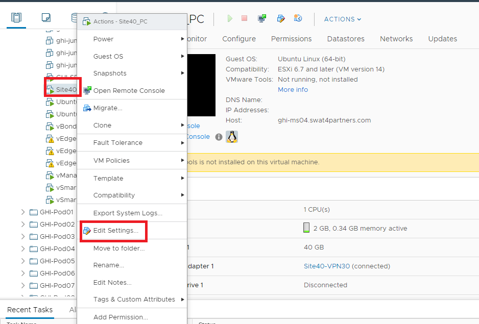
Back at the vCenter screen, right click on the Site40PC (named sdwan-sjc/ghi-site40pc-podX) for your POD and click on Edit Settings (image as an example only)
-
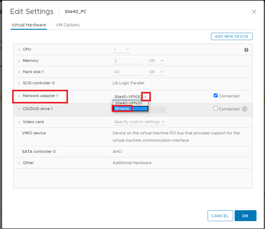
Under Network Adapter 1 click on the drop down and click Browse
-
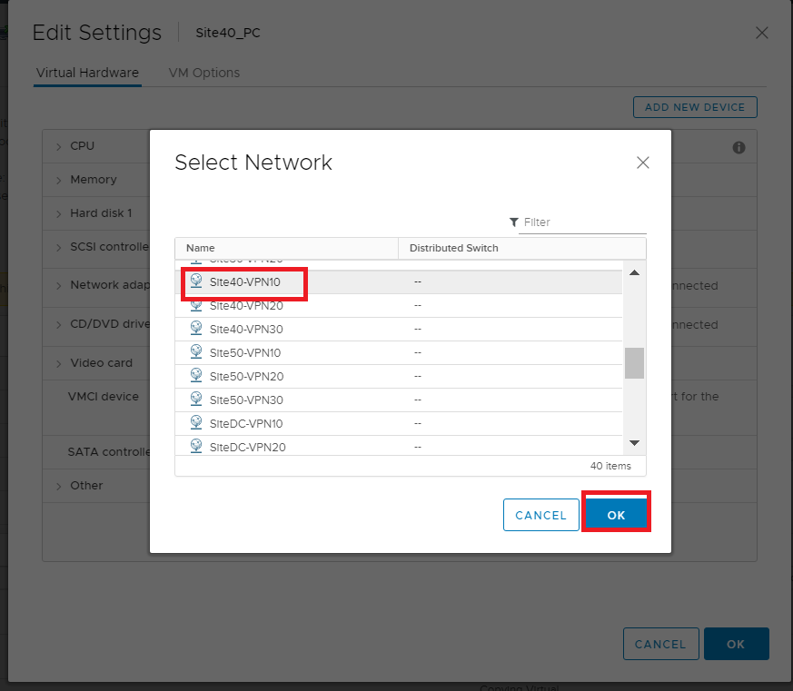
Select Site40-VPN10 from the list of Networks and click on OK. Click on OK again.
-
Log in to the cEdge40 CLI via Putty and issue
clear policy-map counters. Confirm that you want to clear the counters. Now issue ashow policy-map interface Gig2and ashow policy-map interface Gig3. You will notice the number of packets incrementing in Queue0 (this includes VoIP packets via configuration and Control packets by default). Run the two commands given above multiple times and take notice of Queue3 and Queue0. Queue3 should not increment, whereas Queue0 will keep incrementing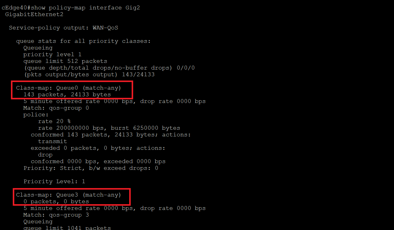
show policy-map interface Gig2 show policy-map interface Gig3 -
Go back to the Site 40 PC and open Terminal. Type
ping 10.100.10.2. Let the pings run for a few seconds, making note of how many packets did we receive a response for (look at the icmp_seq field) and then stop the pings by pressing Ctrl + C. We let the ping run for 70 packets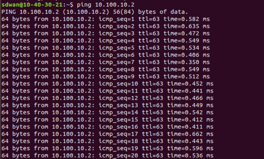
-
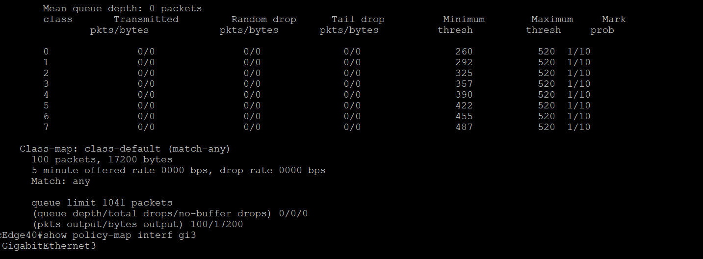
Issue
show policy-map interface Gig2andshow policy-map interface Gig3again on the cEdge40 CLI. Queue3 in one of the outputs (depends on the path taken by the packets) should reflect an increment in the number of packets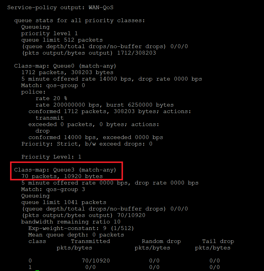
Thus, traffic is being matched as per our QoS strategy. However, we won’t be able to test other queues since ESXi (the VMWare environment in which our lab is running) doesn’t allow packet tags to be propagated over Standard vSwitches (the virtual switch). Queue0 shows up since this traffic is generated natively by the Router in question.
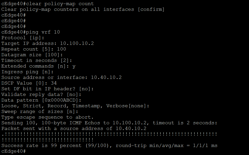
An extended ping directly from the Router yields unpredictable results, with traffic usually getting matched to class class-default (optional - you can try this out).
This completes our QoS activity verification.