- Creating the Site 20 Feature Templates
- Creating the VPN0 Feature Template
- Creating the INET and MPLS VPN Interface Feature Template
- Modifying a Device Template and Attaching Devices
Overview
We can take the Feature Templates created for the DC-vEdges and use them as a starting point for configuring the Feature Templates at Site 20. Necessary changes based on the topology will need to be made (for example, things like a single uplink at the Site20 devices vs. a dual uplink at the DC devices)
Creating the Site 20 Feature Templates
Creating the VPN0 Feature Template
We will set up the VPN templates for VPN 0 in Site 20 by making a copy of the DCvEdge-vpn0 Feature Template created before
-
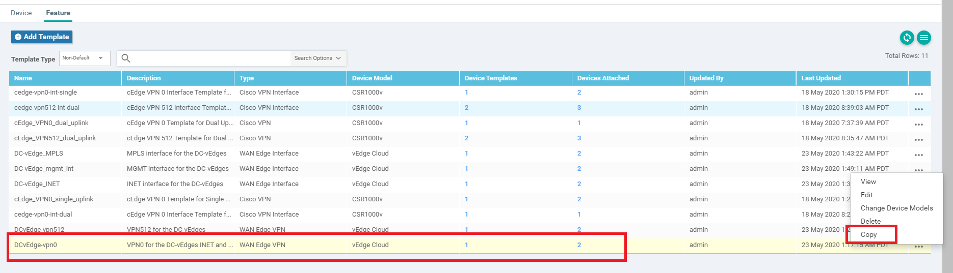
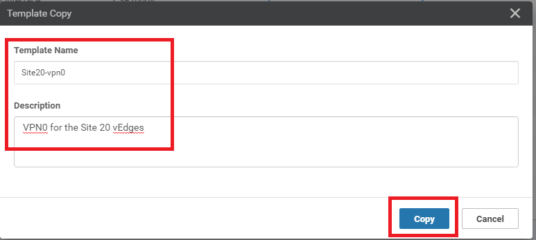
Identify the DCvEdge-vpn0 Feature Template from Configuration => Templates => Feature tab. Click on the three dots in the extreme right-hand side of the template and click Copy. Name it Site20-vpn0 with a Description of VPN0 for the Site 20 vEdges. Click on Copy again
-
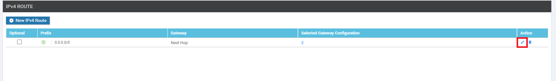
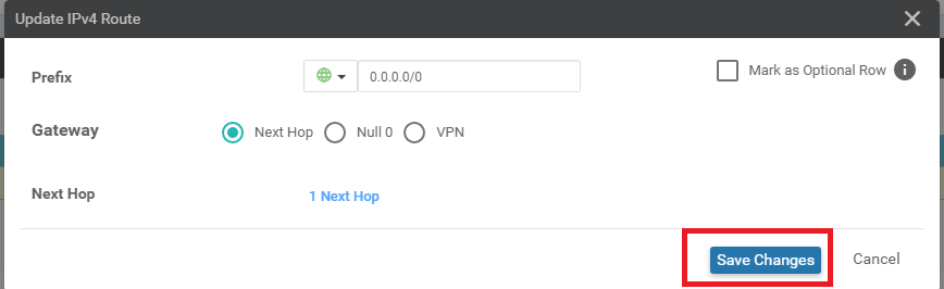
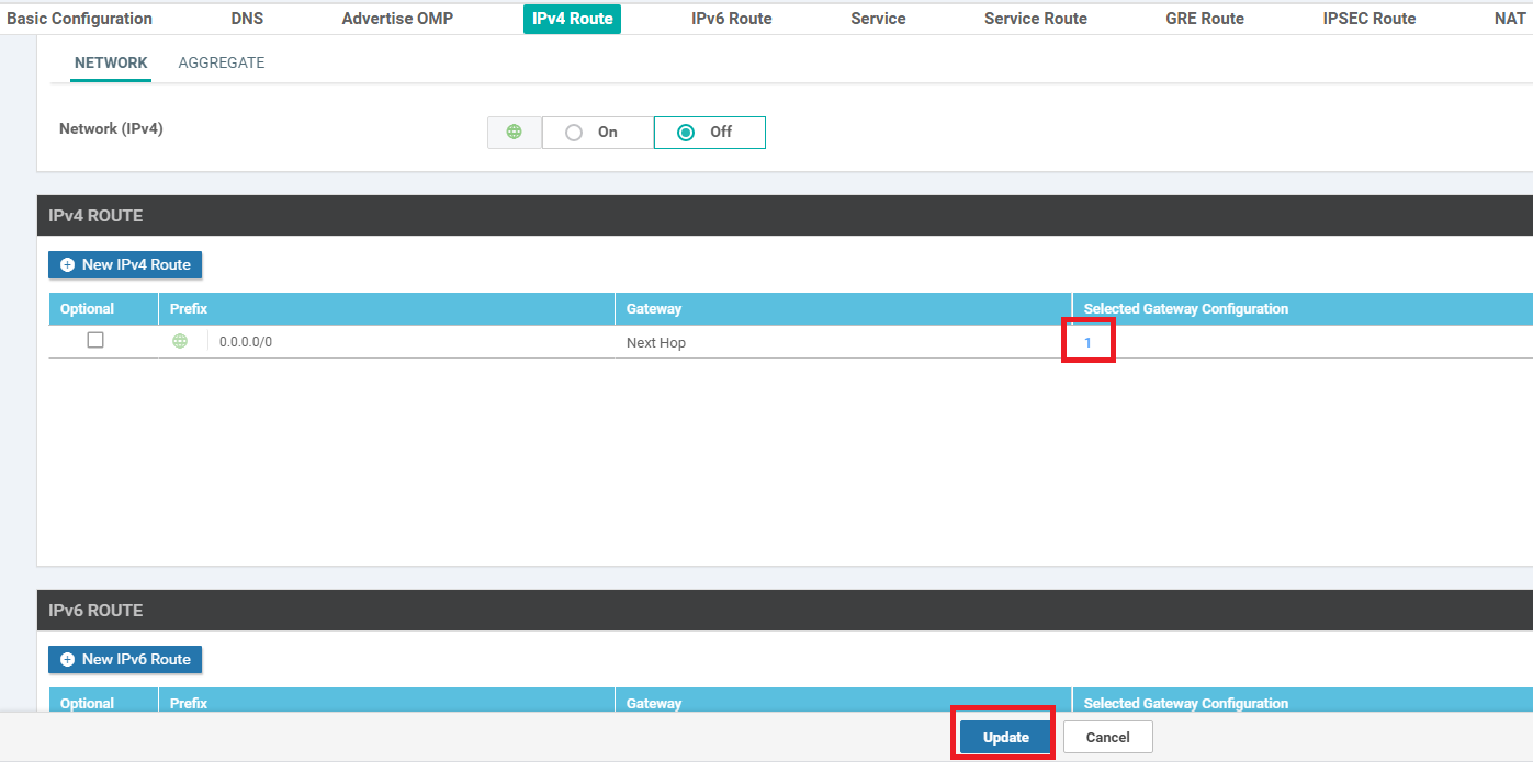
Locate the Site20-vpn0 template just created and click on the three dots at the end of it. Click on Edit. Identify the IPv4 Route section - there should be a route populated there for 0.0.0.0/0. Edit this route by clicking on the pencil icon
-
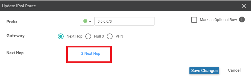
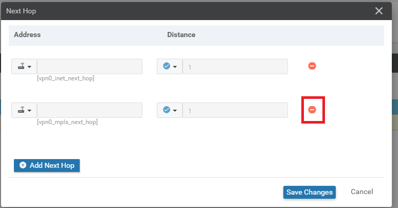
Click on 2 Next Hop
-
Click on the remove icon for the second next hop
-
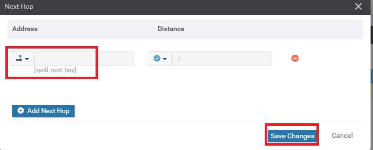
Edit the name of the INET next hop to represent something more generic, like vpn0_next_hop. We will use this VPN0 Template for both the vEdges at Site 20. Click on Save Changes
-
Make sure there is just 1 Next Hop populated and click on Save Changes again
-
Click on Update on the main Feature Template screen
This completes the configuration of the VPN 0 Feature Template for Site 20.
- Creating the Site 20 Feature Templates
-
- Creating the INET and MPLS VPN Interface Feature Template
- Modifying a Device Template and Attaching Devices
Creating the INET and MPLS VPN Interface Feature Template
We will copy and edit the DC-vEdge_MPLS Interface Feature Template for our INET and MPLS VPN Interface Feature Templates at Site 20.
-
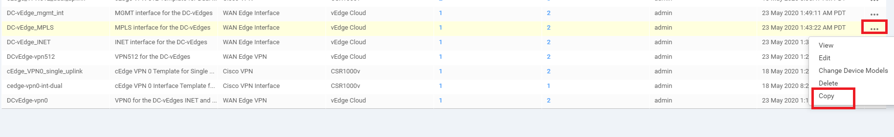
Navigate to the Configuration => Templates section and make sure you’re on the Feature tab. Click on the three dots next to the DC-vEdge_MPLS and click on Copy
-
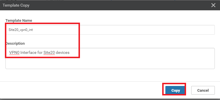
Rename the Template to Site20_vpn0_int and the Description as VPN0 Interface for Site20 devices. Click on Copy
-
Edit the newly created template by clicking on the 3 dots next to it and choosing Edit. Update the details as per the table below, referencing the screenshots. Click on Update once done
Section Field Global or Device Specific (drop down) Value Template Name NA Site20_vpn0_int Description NA VPN0 Interface for Site20 devices Basic Configuration Shutdown Global No Basic Configuration Interface Name Device Specific vpn0_if_name Basic Configuration IPv4 Address Device Specific vpn0_if_ip_add Tunnel Tunnel Interface Global On Tunnel Color Device Specific vpn0_if_color Tunnel Restrict Device Specific vpn0_if_color_restrict Tunnel - Allow Service All Global On 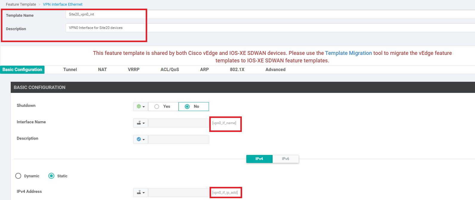
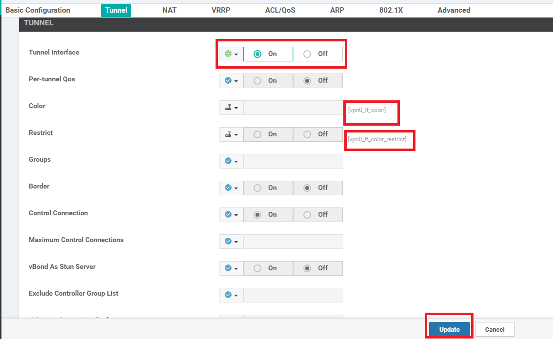
We have completed configuring the VPN 0 Interface Template for the Site 20 Devices. This template will be used for the INET and MPLS links at Site 20. Notice how easy it has become to add configuration, once the initial template has been built?
-
-
-
- Modifying a Device Template and Attaching Devices
Modifying a Device Template and Attaching Devices
-
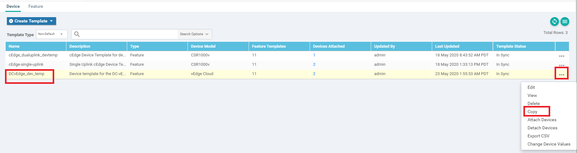
Go to Configuration => Templates and make sure you’re on the Device tab. Click on the three dots next to the DCvEdge_dev_temp. Click on Copy
-
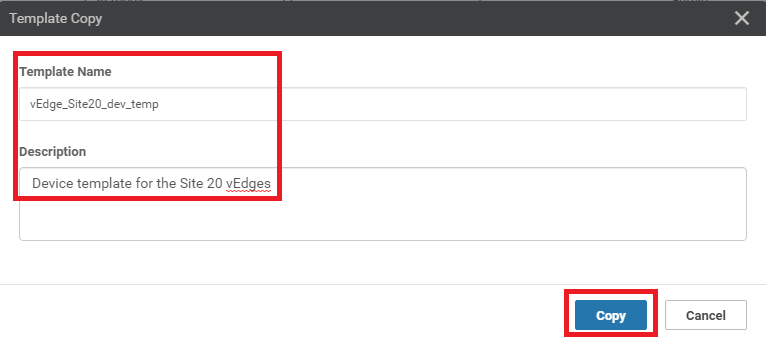
Rename the Template vEdge_Site20_dev_temp and give it a Description of Device template for the Site 20 vEdges. Click on Copy
-
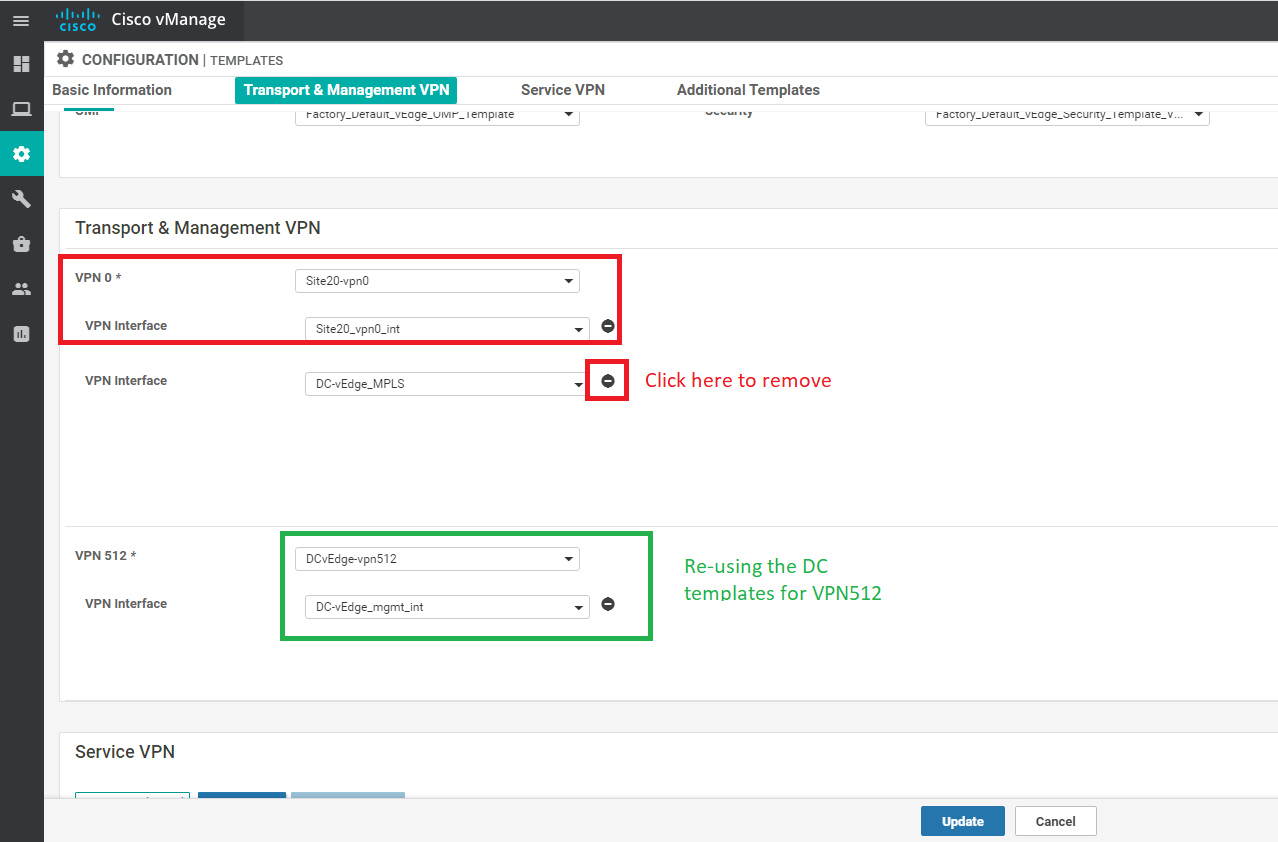
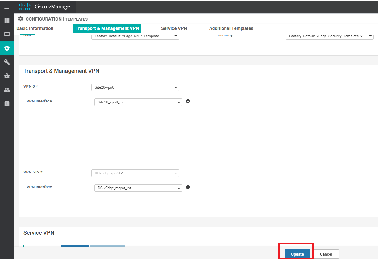
Click on the three dots next to the newly created template and click on Edit. Update the Transport and Management VPN section as per the screenshot below. Remember to remove the 2nd VPN Interface under VPN 0. We will be re-using the VPN 512 Templates created for the DC-vEdges.
-
Click on Update once done
-
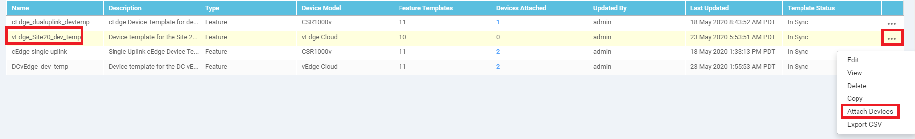
Click on the three dots next to the newly created vEdge_Site20_dev_temp Template and click on Attach Devices
-
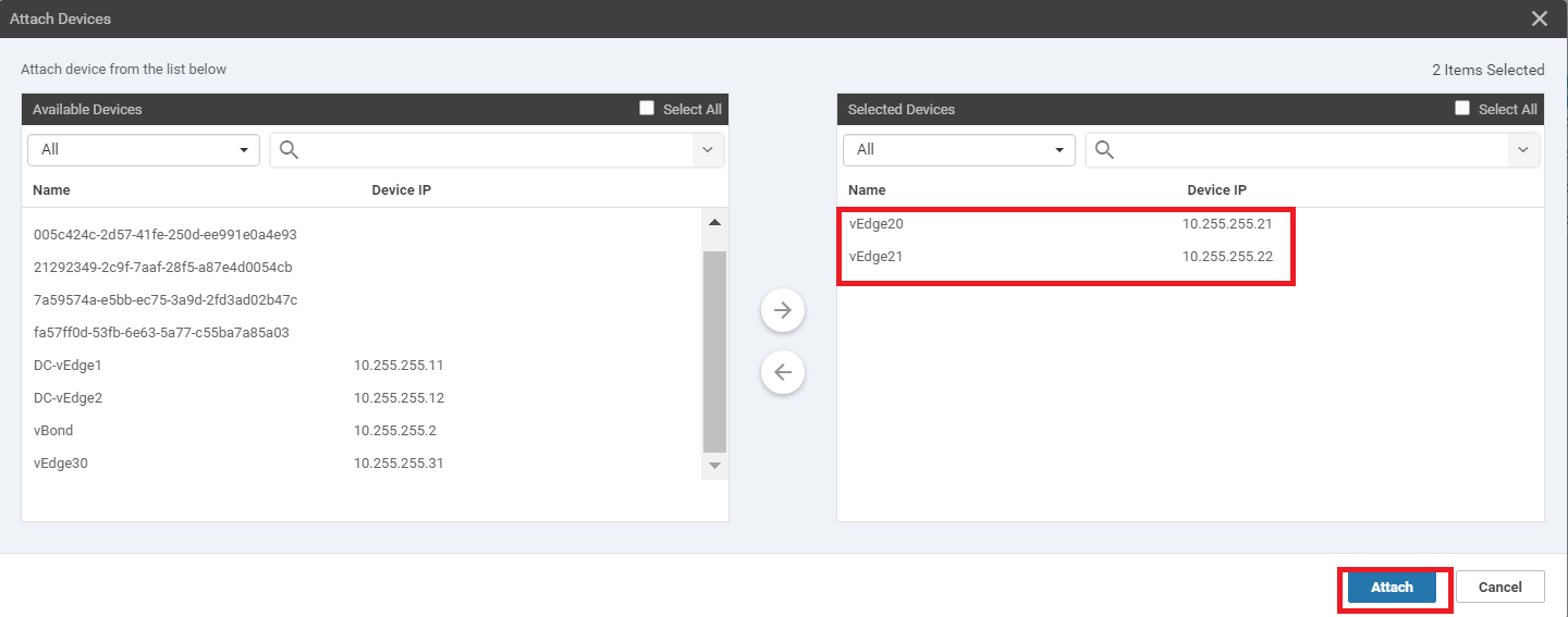
Choose vEdge20 and vEdge21 from the list and click on Attach
-
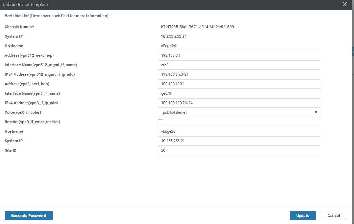
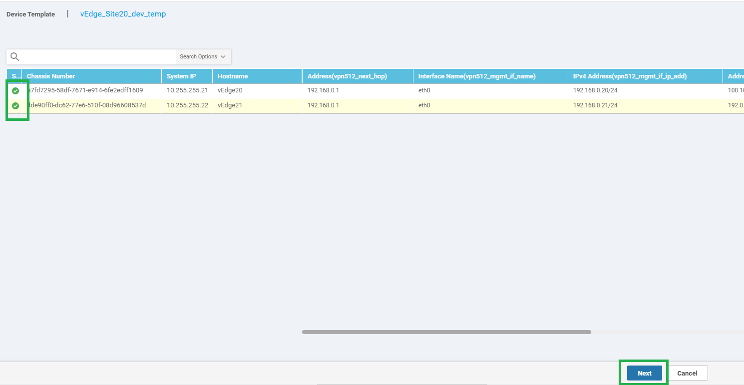
The two devices should show up in the list. Click on the three dots next to vEdge20 and choose to Edit Device Template. Populate the details as shown below and click on Update
-
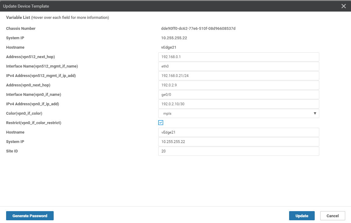
Similarly, click on the dots next to vEdge21 and choose to Edit Device Template. Populate the details as shown below and click on Update
-
Both devices should now have a check mark next to them. Click on Next
-
You can click on Configure Devices or choose to view the Side-by-Side Config Diff by clicking on the Device, choosing the Config Diff box and then clicking on Side by Side. Click on Configure Devices
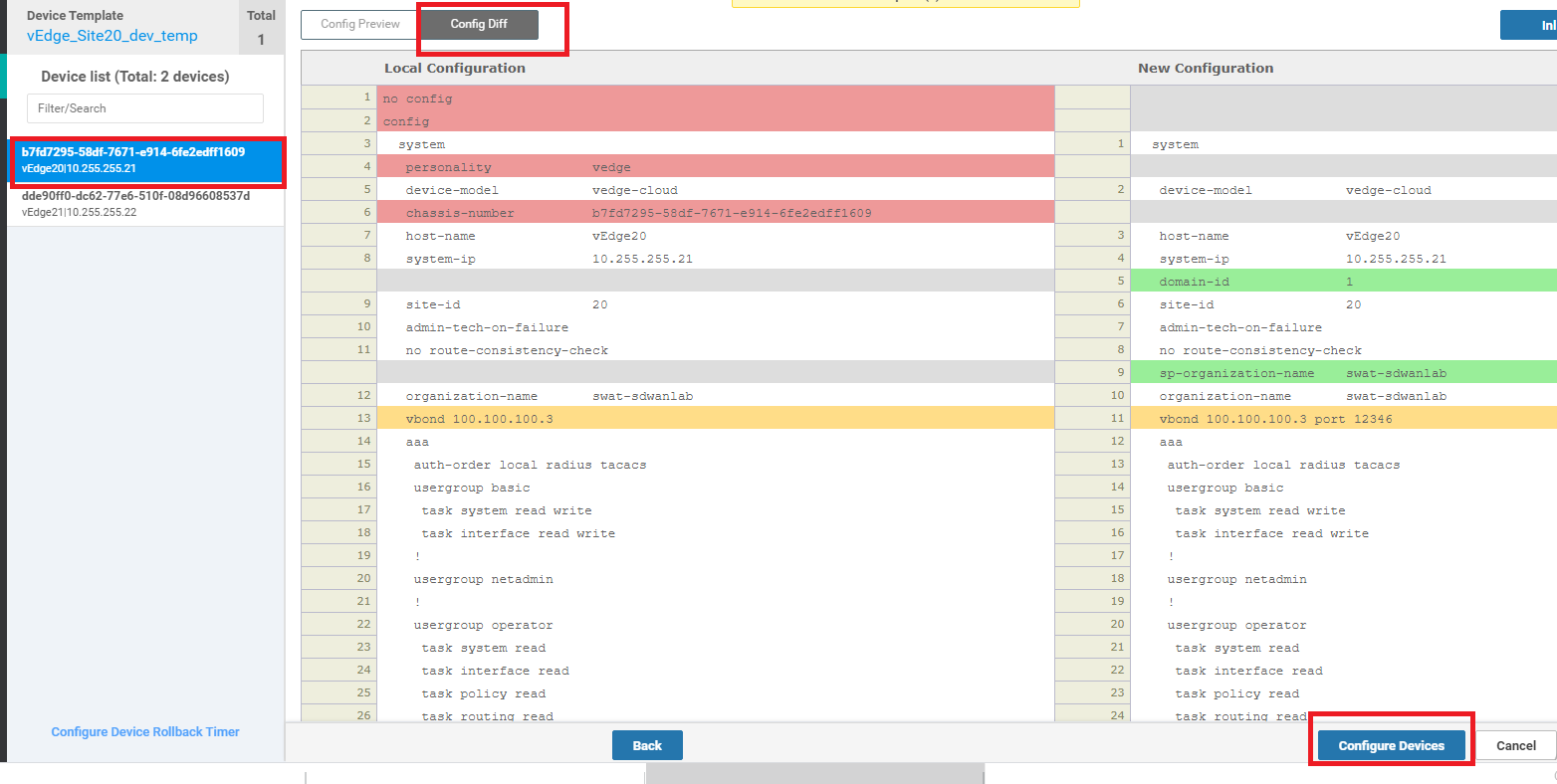
-
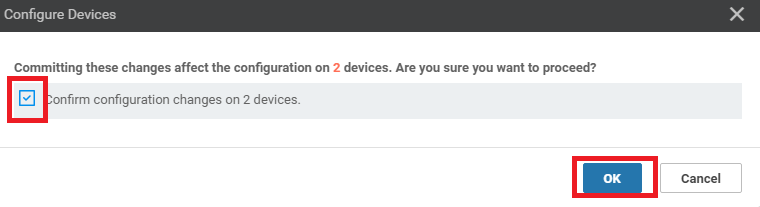
Confirm this change and click on OK
-
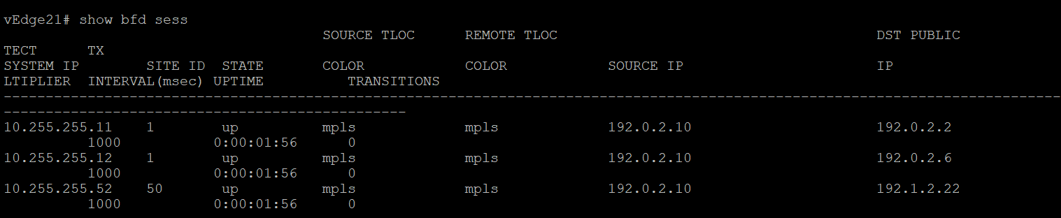
Once the configuration updates have gone through successfully, log in to the CLI for vEdge21 and issue a
show bfd sessions. You can also check this from the GUI by navigating to Monitor => Network, clicking on vEdge21 and choosing Real-Time => BFD Sessions in the Device Options. Choose Do Not Filter.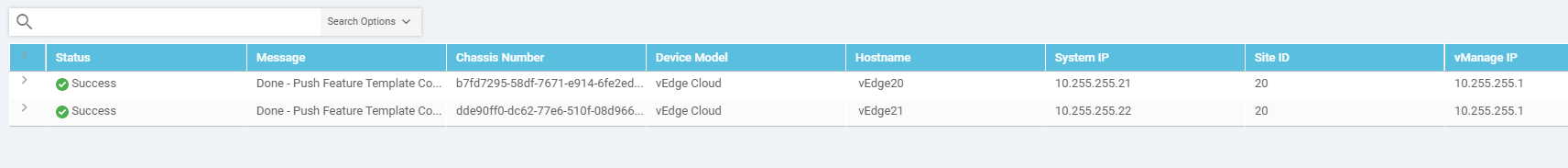
-
On the vManage GUI, navigate to Configuration => Devices and you should see the two vEdges at Site 20 in vManage mode

We have successfully placed the devices in Site 20 under the control of vManage.