- Overview
- Adding WAAS Nodes to WCM
- Downloading vManage certs and Enabling DIA at Site DC
- Integrating vManage and WCM
- Discovering the AppNav-XE Controllers
- Setting up the AppNav Clusters
- Verification and Testing
Overview
Cisco WAAS and SD-WAN can be integrated for traffic interception and redirection to WAAS Nodes for optimization. This brings WAAS capabilities to Cisco IOS-XE SD-WAN by enabling the AppNav-XE feature on compatible devices.
Cisco SD-WAN Devices are configured with AppNav-XE redirection policies and WAAS nodes are configured with optimization policies from WAAS Central Manager (WCM).
The AppNav-XE SD-WAN Device and the WAAS Nodes together form a cluster known as an AppNav-XE cluster.
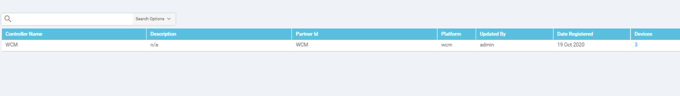
The WCM registers as a third party controller to vManage.
The components of the WAAS SD-WAN solution are:
- WAAS Central Manager (WCM) - used for centralized management of WAAS Nodes and AppNav-XE on Cisco SD-WAN Devices
- AppNav-XE Service Controller (SC) running on WAN Edges which contain redirection policies
- WAAS Nodes or Service Nodes (SN) which contain optimization policies
-
- Adding WAAS Nodes to WCM
- Downloading vManage certs and Enabling DIA at Site DC
- Integrating vManage and WCM
- Discovering the AppNav-XE Controllers
- Setting up the AppNav Clusters
- Verification and Testing
Adding WAAS Nodes to WCM
-
Open the WCM GUI by navigating to the IP Address of WCM (10.100.10.100) or using the bookmark on your Jumphost and entering the credentials as enumerated below
Username Password admin default 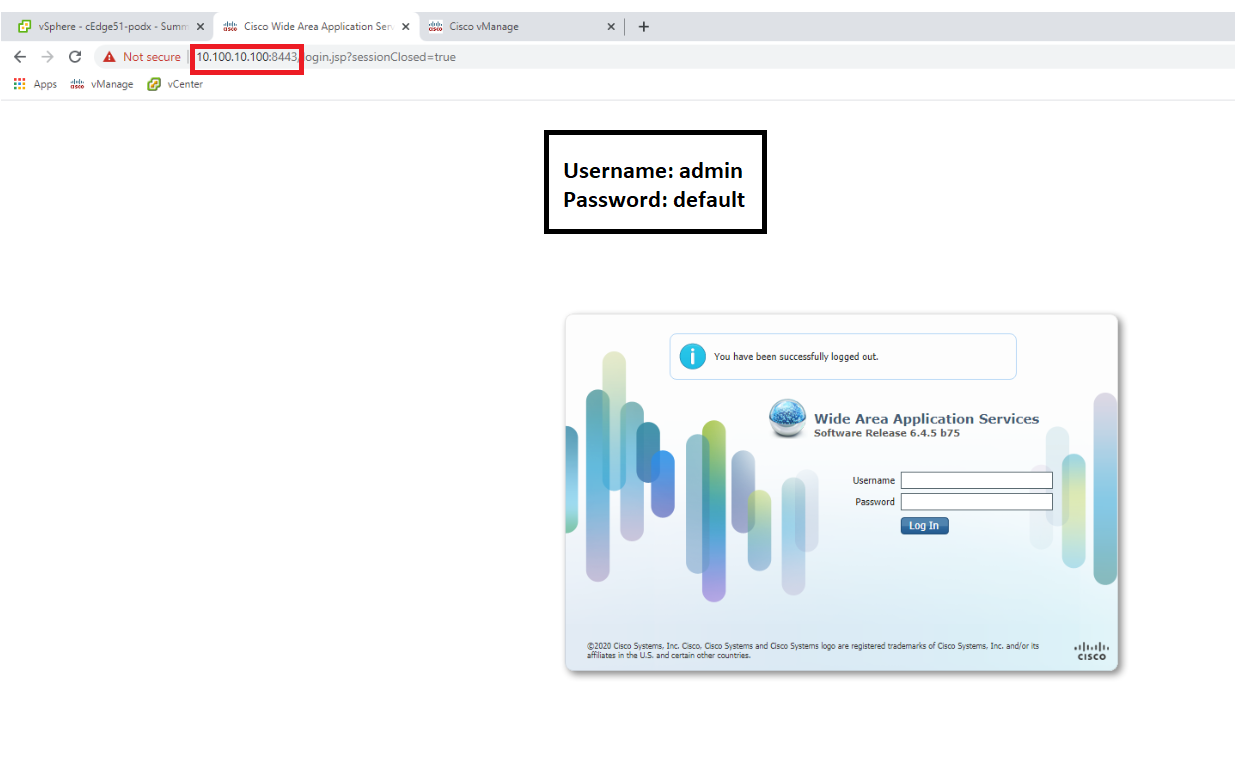
-
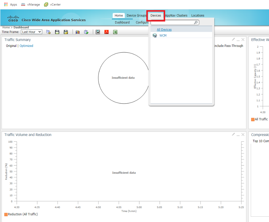
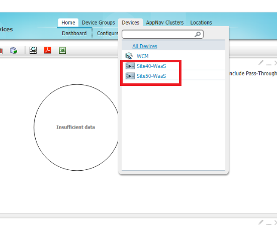
Once logged in, click on Device and notice that there aren’t any nodes added to WCM as of now. We will be adding the WAAS Nodes to WCM in this section
-
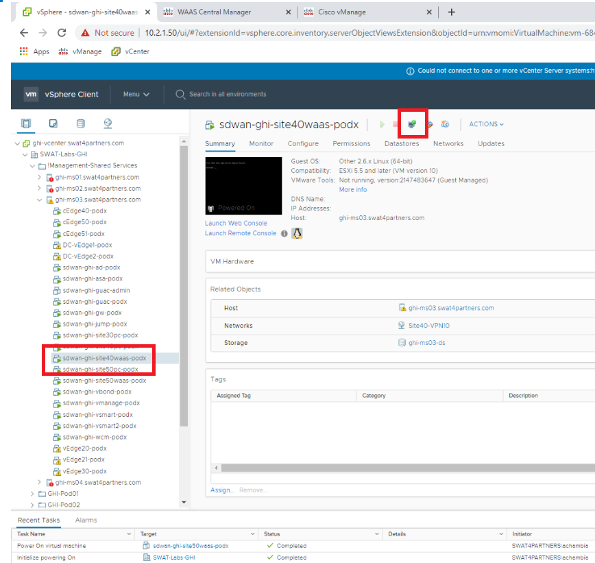
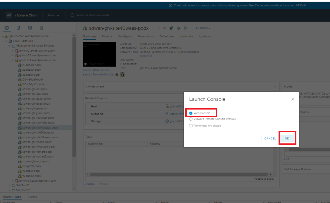
Open vCenter (10.2.1.50/ui if connected to the GHI DC and 10.1.1.50/ui if connected to the SJC DC or via the bookmark) and log in using the credentials provided for your POD. Locate the sdwan-sjc/ghi-site40waas VM and click on it. Click on the Open Console icon and choose Web Console if prompted. Click on OK. Initial setup of the WAAS Nodes is done via the CLI
-
Enter the username and password as enumerated below to log in to the WAAS Node
Username Password admin default 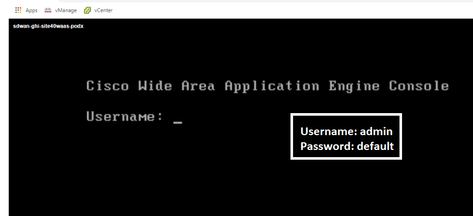
-
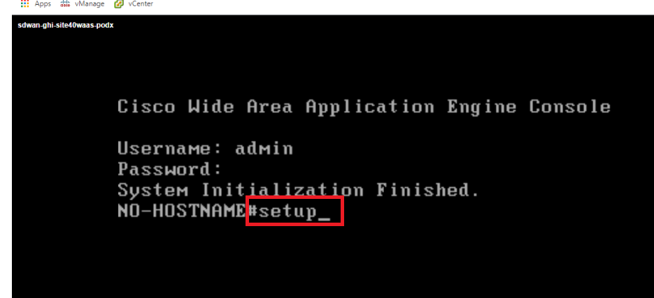
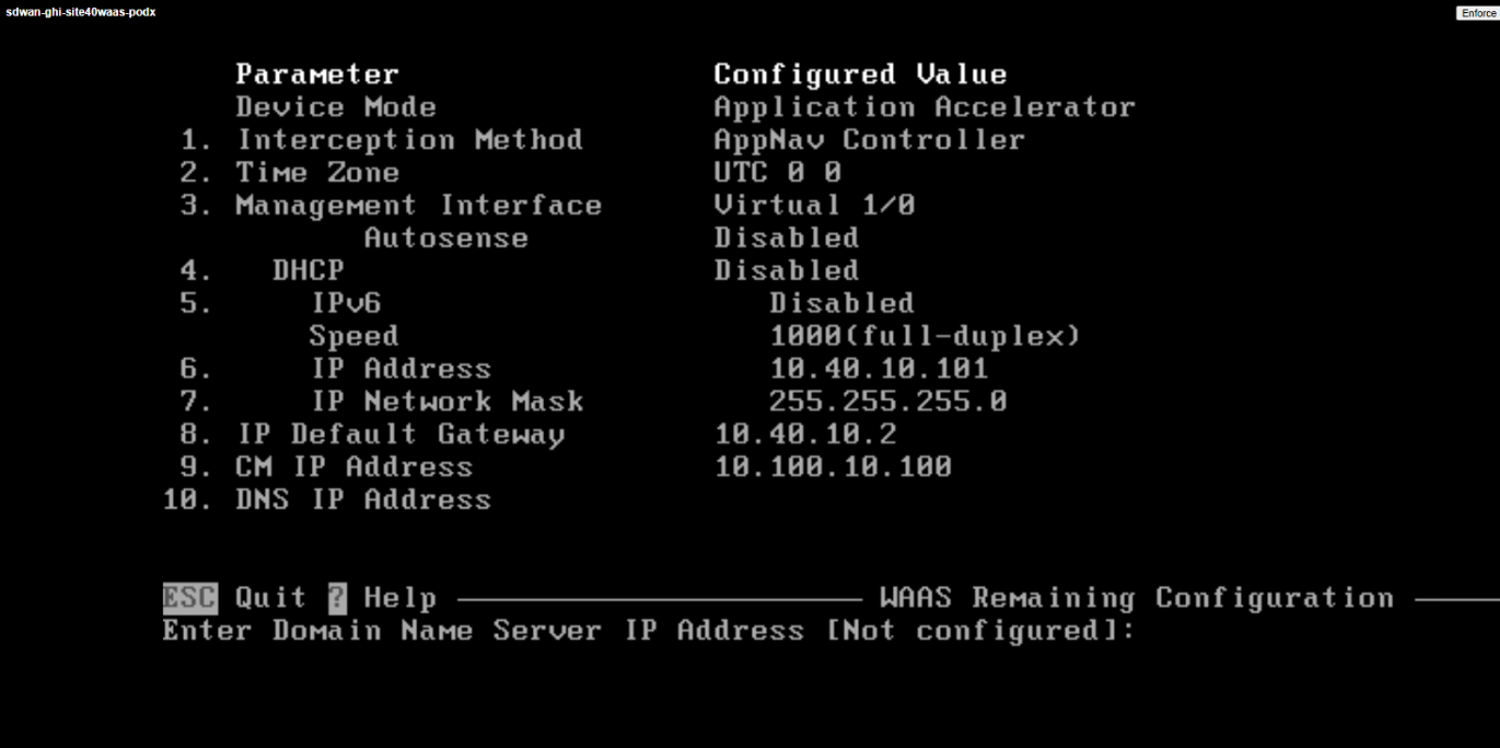
Type setup and hit Enter to begin initial setup of the WAAS Node
-
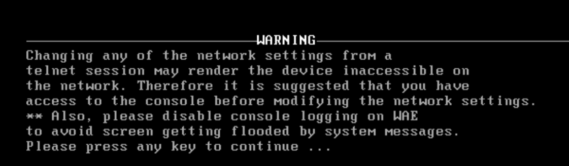
Press any key to continue
-
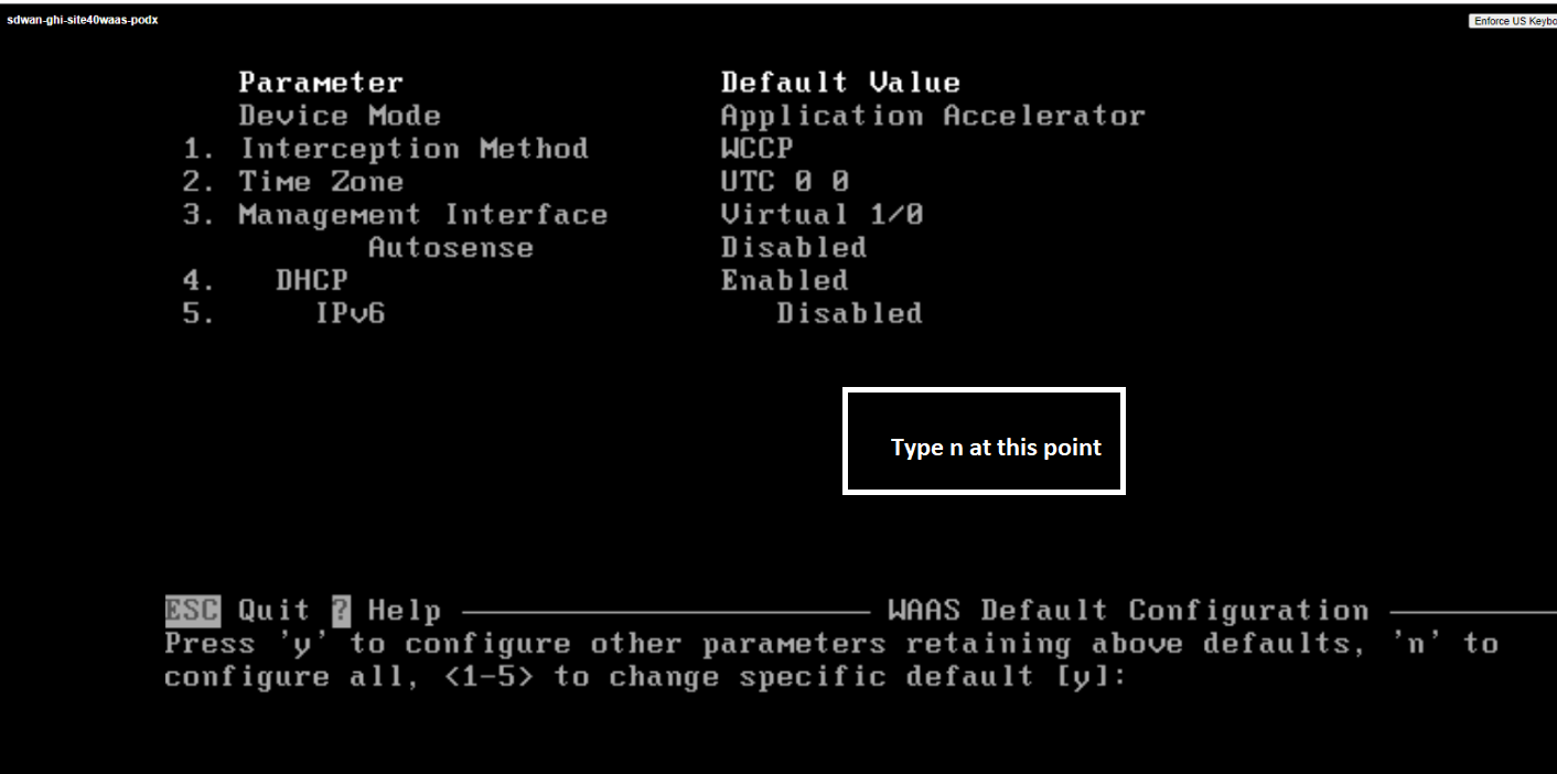
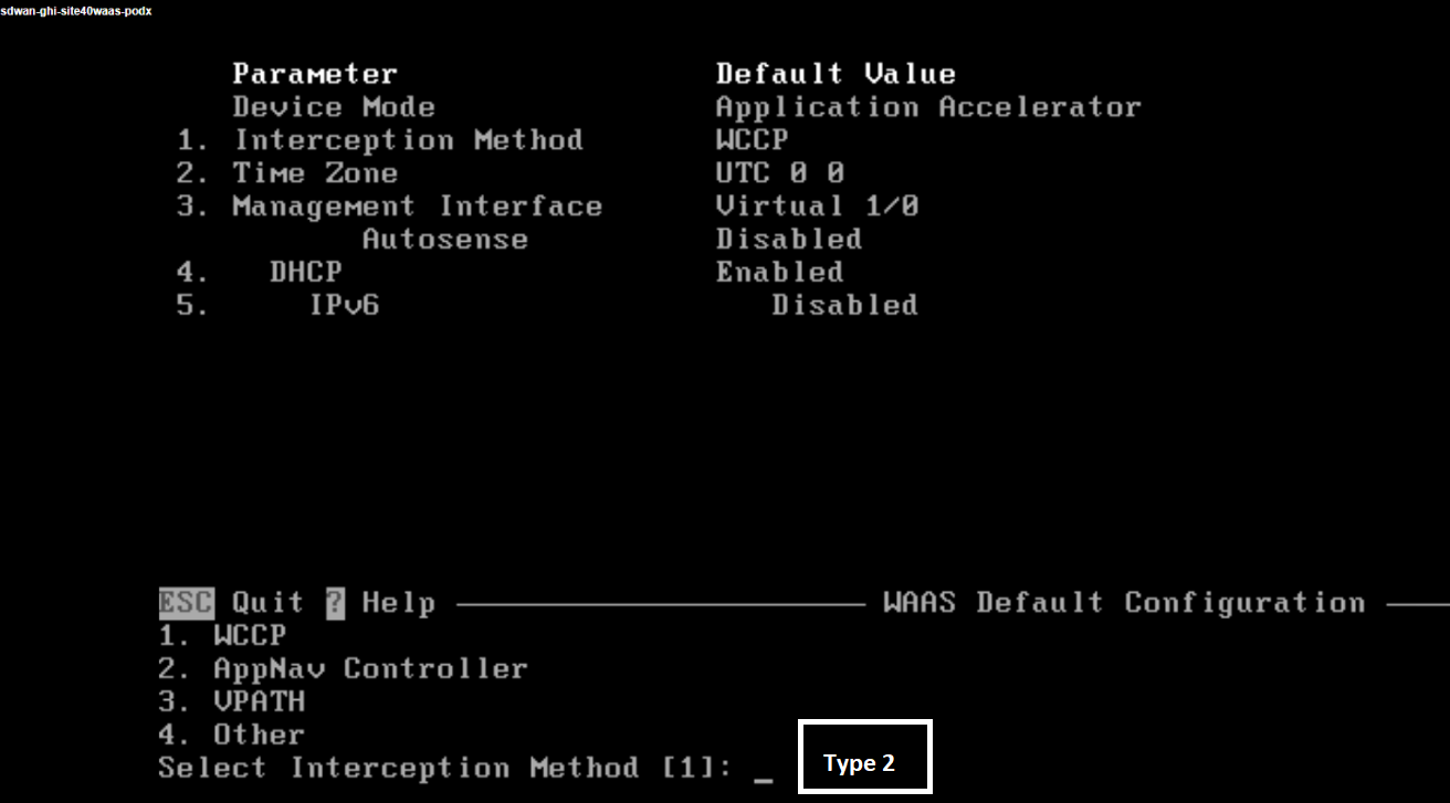
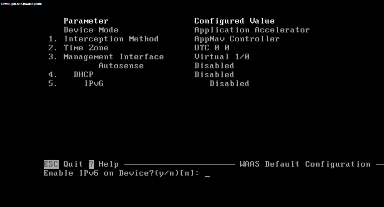
We will now be presented with a few ways in which the node can be configured. Type n to begin configuring all parameters of the WAAS Node. In some of the prompts during this setup, you don’t need to press Enter for the input to take effect
-
At the Select Interception Method type 2 to set the interception method to AppNav. This is the only supported interception method in SD-WAN WAAS
-
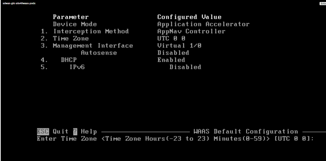
Hit Enter at the Enter Time Zone prompt to choose the default time zone of UTC
-
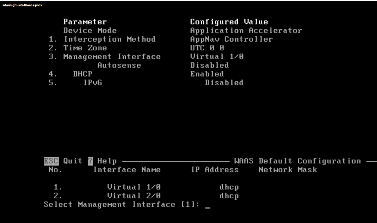
Hit Enter at the Select Management Interface prompt to select Virtual 1/0 as the management interface
-
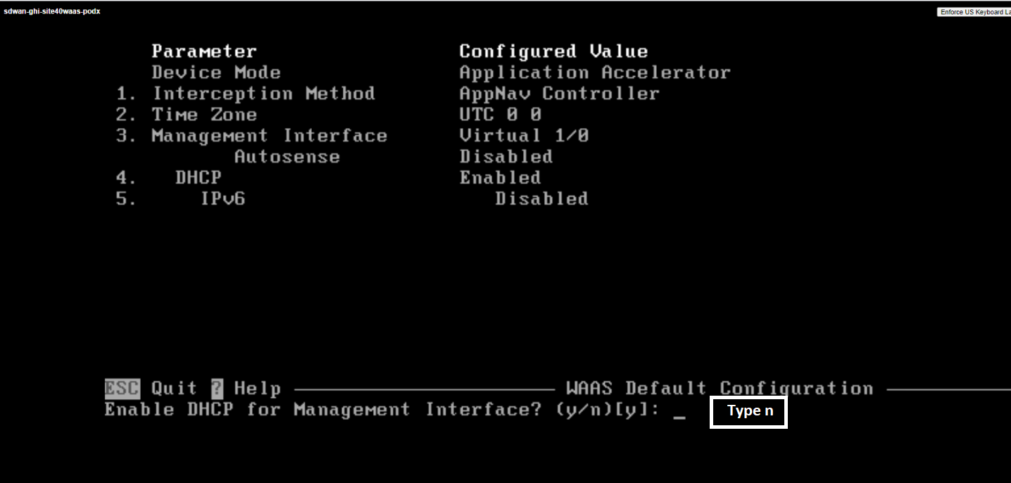
Type n at the Enable DHCP for Management Interface to disable DHCP on the selected management interface. We will be entering an IP Address manually
-
Hit Enter at the Enable IPv6 on Device prompt such that IPv6 is not enabled
-
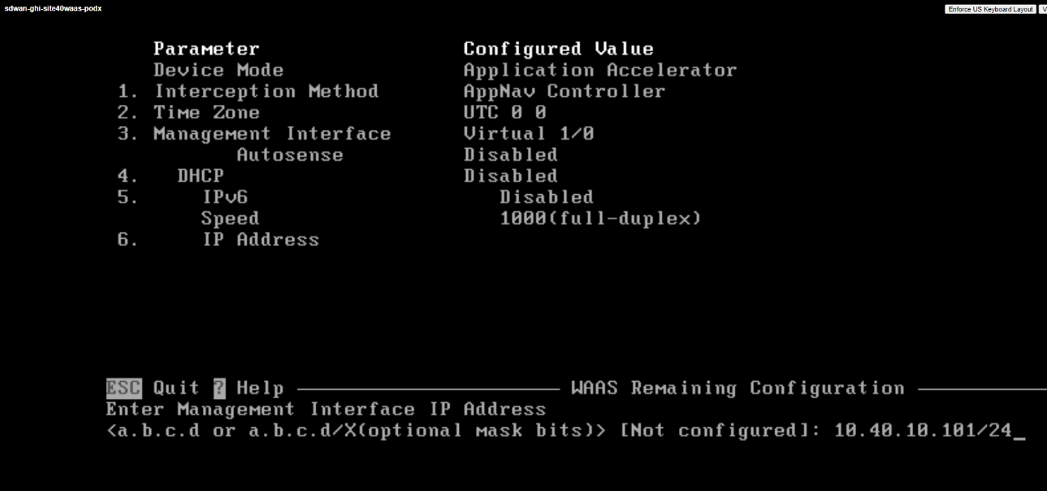
Type an IP Address of 10.40.10.101/24 and hit Enter
-
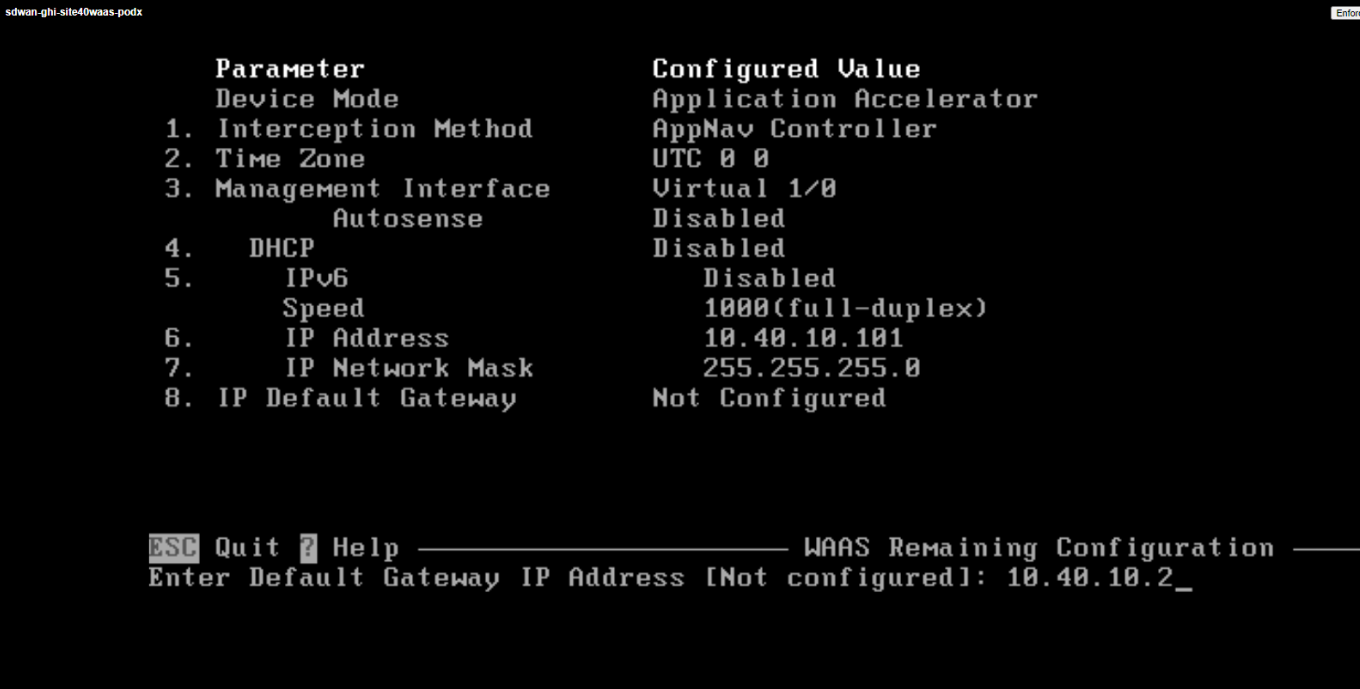
Type a Default Gateway address of 10.40.10.2 and hit Enter
-
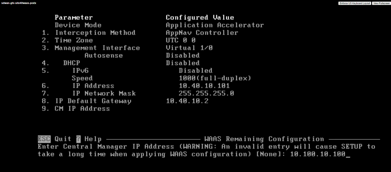
Type 10.100.10.100 at the Enter Central Manager IP Address prompt and hit Enter
-
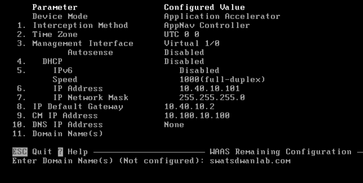
Hit Enter at the Enter Domain Name Server IP Address prompt. We will not be using DNS
-
Type swatsdwanlab.com at the Enter Domain Name(s) prompt and hit Enter
-
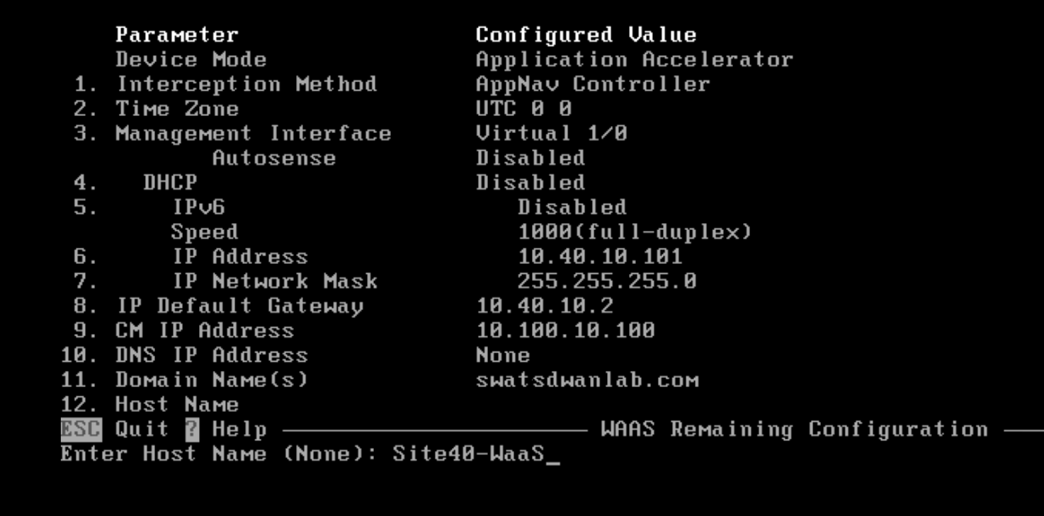
Type Site40-WaaS as the Hostname and hit Enter
-
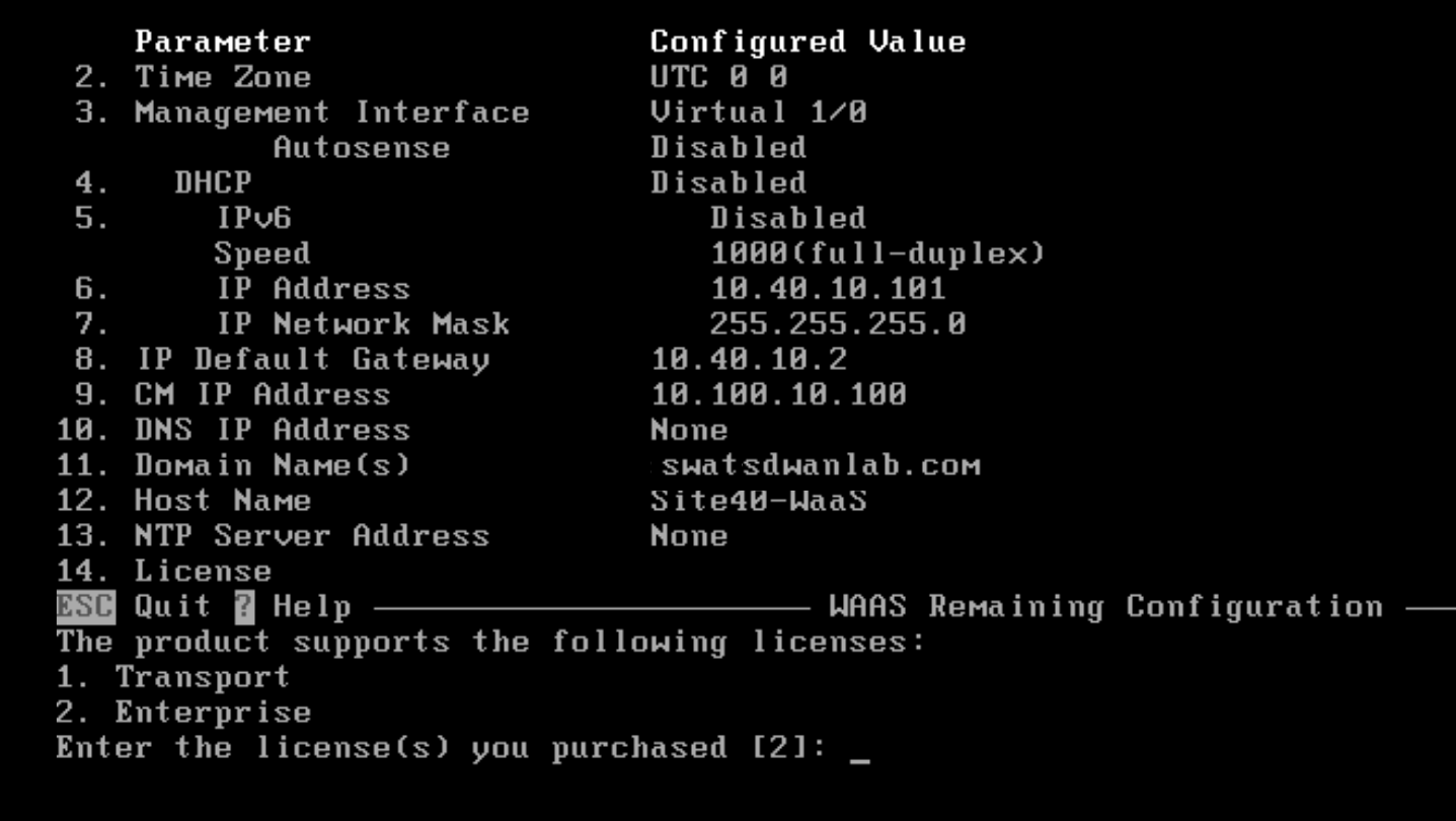
Hit Enter when asked about the license to accept the default of Enterprise Licenses
-
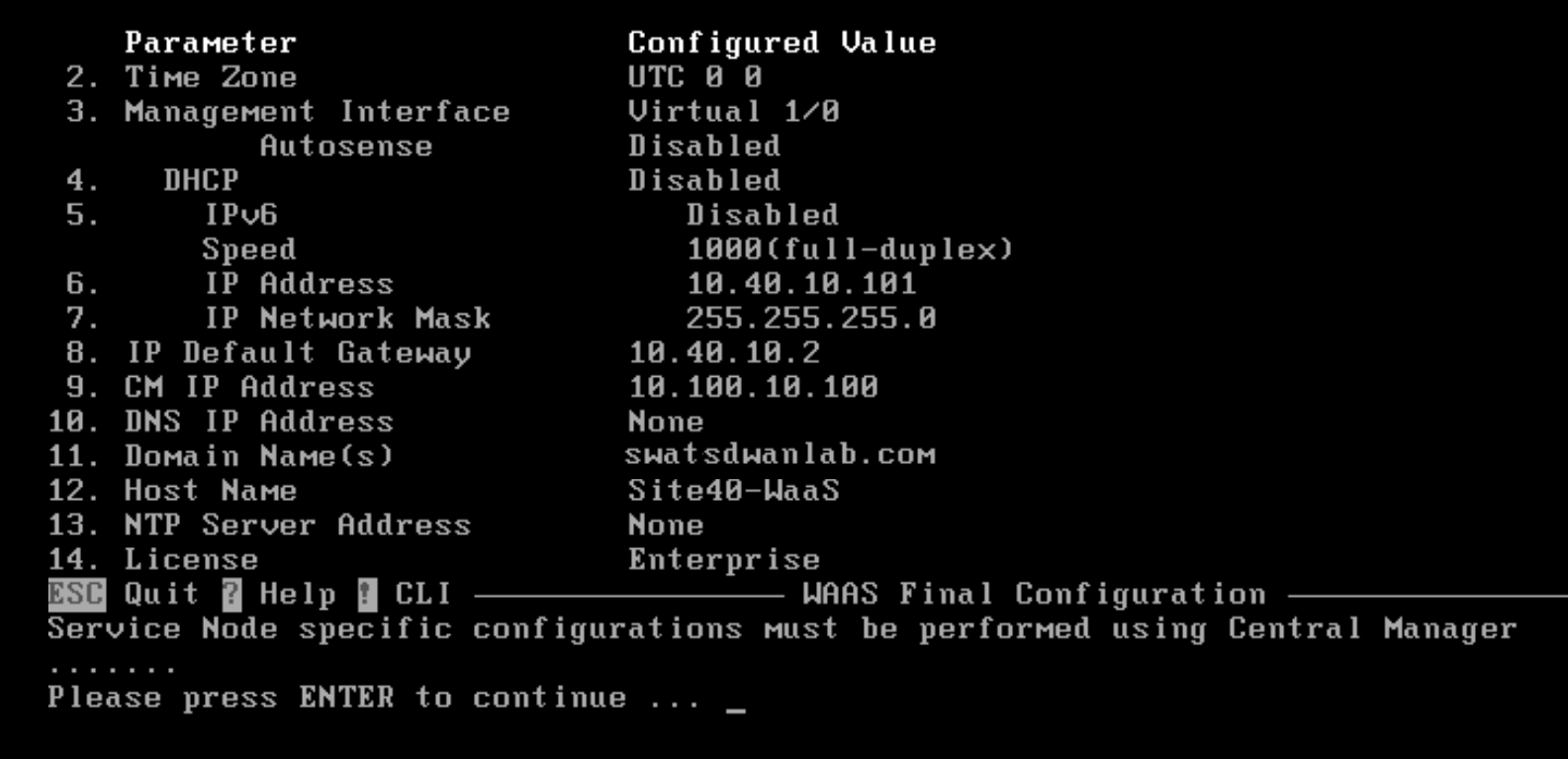
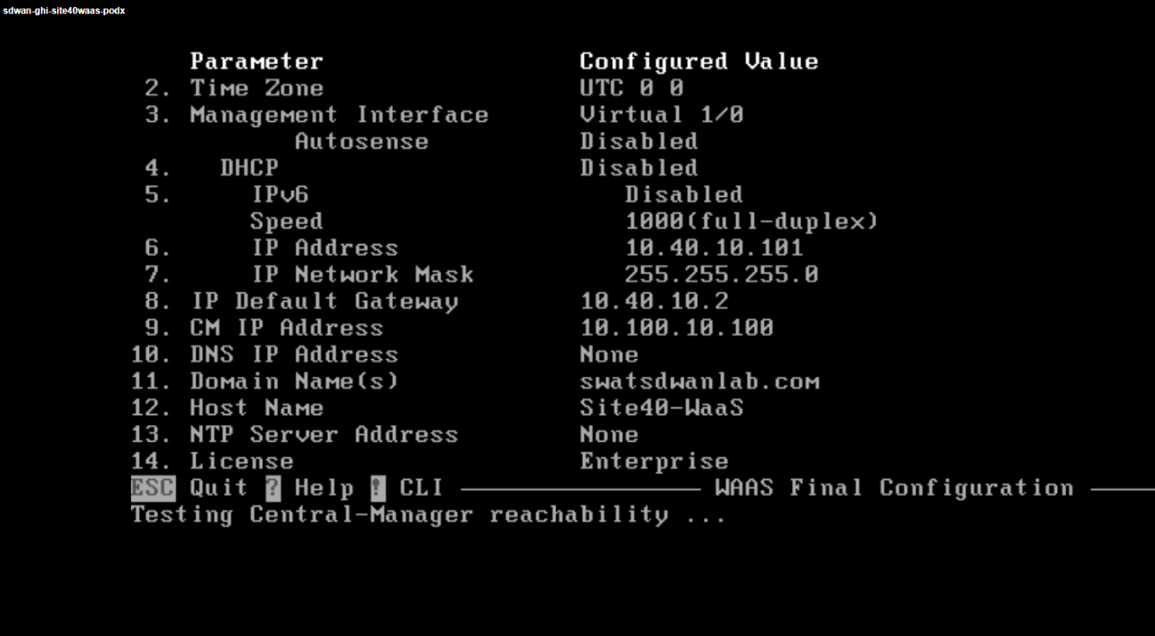
Hit Enter to implement the configuration changes
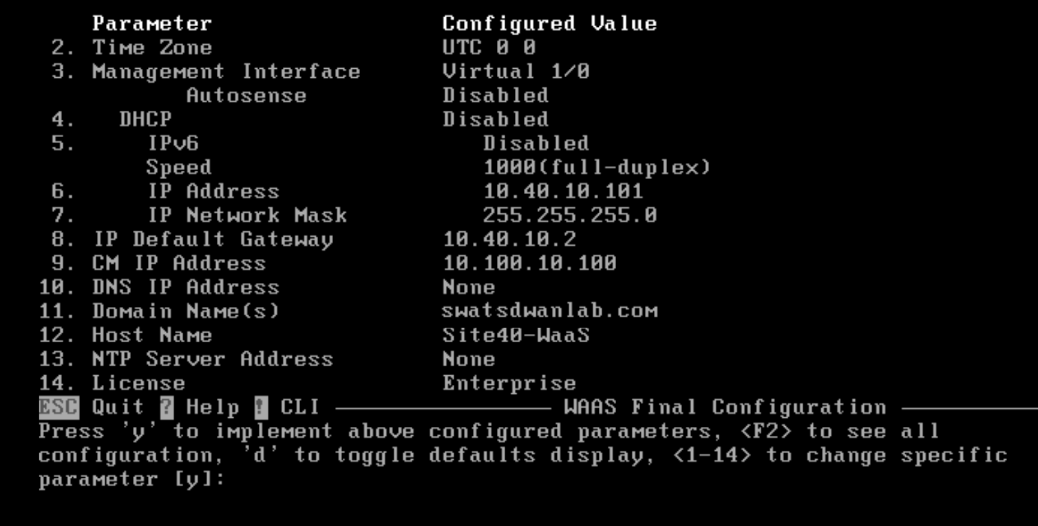
-
Hit Enter again
-
Once the connectivity check to WCM passes, hit Enter to skip running diagnostics

-
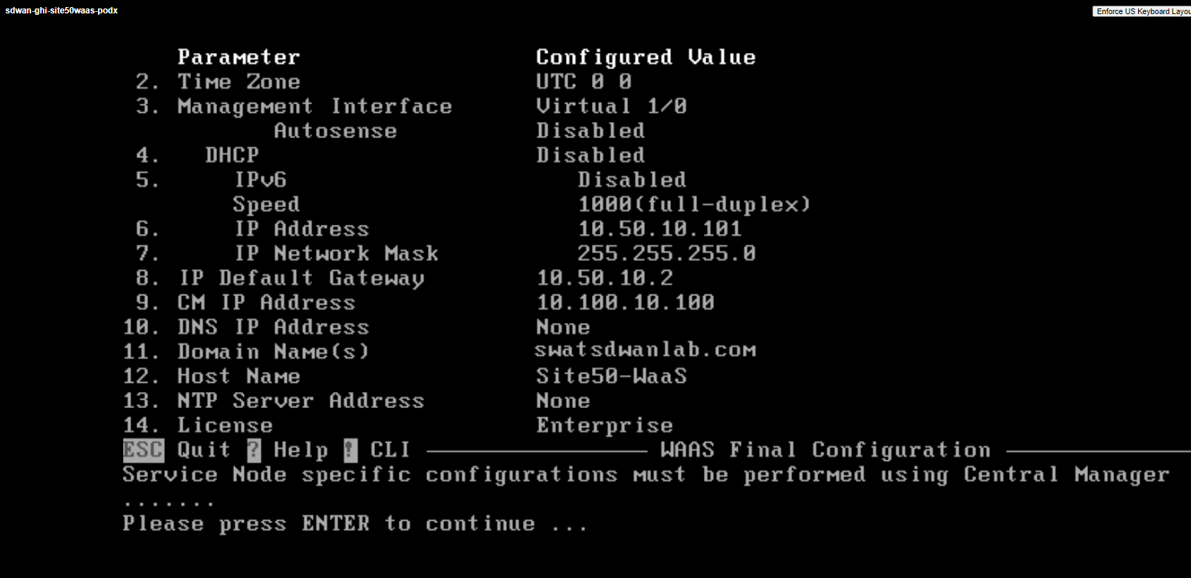
Repeat from Step 3 for the sdwan-sjc/ghi-site50waas node, making necessary changes to the Hostname and IP Address/Default Gateway. All other parameters remain the same. Reference the image given below
-
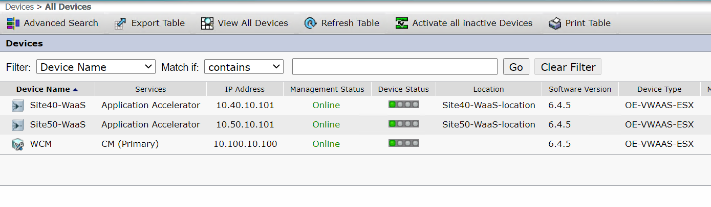
Log in to WCM and navigate to Devices - you should see the two WAAS Nodes we just configured on WCM
-
If you click on All Devices, you will see the Site40-WaaS and Site50-WaaS nodes in an online state. If there are alarms for the Device Status, it’s OK since Core Dump files are generated sometimes
-
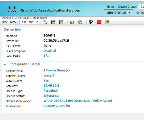
While on the Home page, click on Devices => Site40-WaaS. You will see a WAAS-GLOBAL optimization policy attached to it under Configuration Details. This is the default policy that is attached to all new WAAS Nodes
-
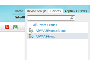
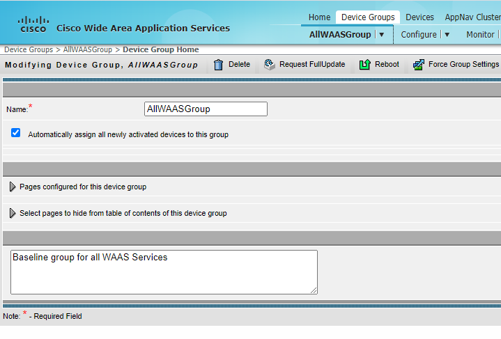
Navigate to Device Groups => AllWAASGroup on the WCM GUI and there will be a check box Automatically assign all newly activated devices to this group which assigns the WAAS Node to this group and hence the WAAS-GLOBAL policy
-
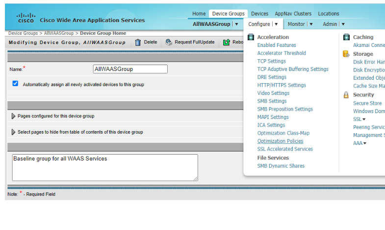
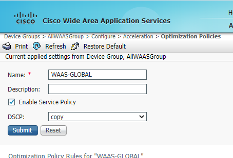
To view the settings of the WAAS-GLOBAL policy, navigate to Configure => Optimization Policies. In the WAAS-GLOBAL policy, click on Restore Default to view the policies
-
Wait for a few seconds and click on Refresh. The policies should now show up. These are the default optimization policies being applied to the WAAS Nodes
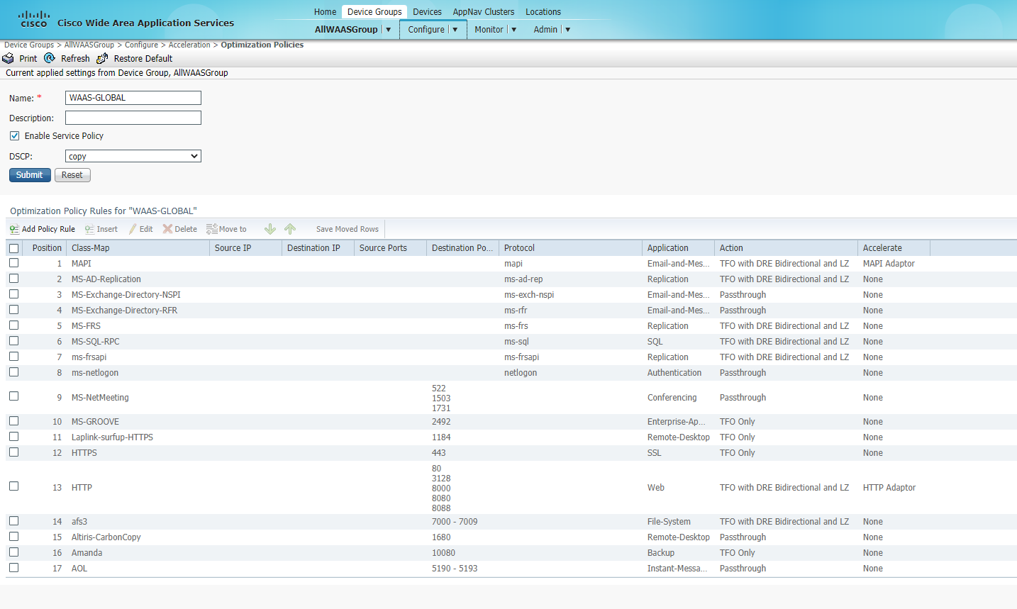
This completes the addition and verification of WAAS Nodes on WCM.
-
-
- Downloading vManage certs and Enabling DIA at Site DC
- Integrating vManage and WCM
- Discovering the AppNav-XE Controllers
- Setting up the AppNav Clusters
- Verification and Testing
Downloading vManage certs and Enabling DIA at Site DC
Go through the following steps in order to prepare for adding the AppNav-XE controllers on WCM.
-
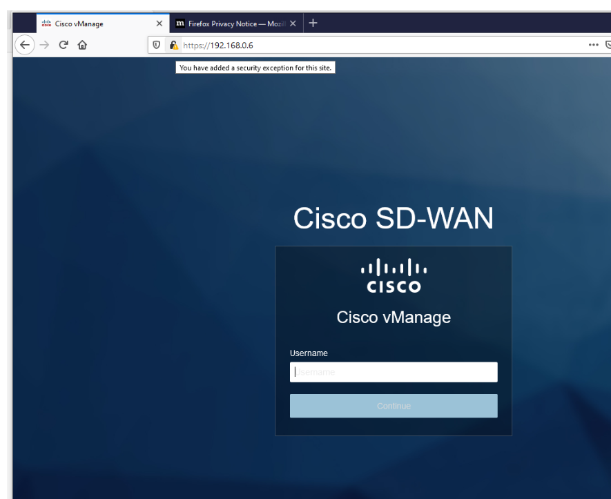
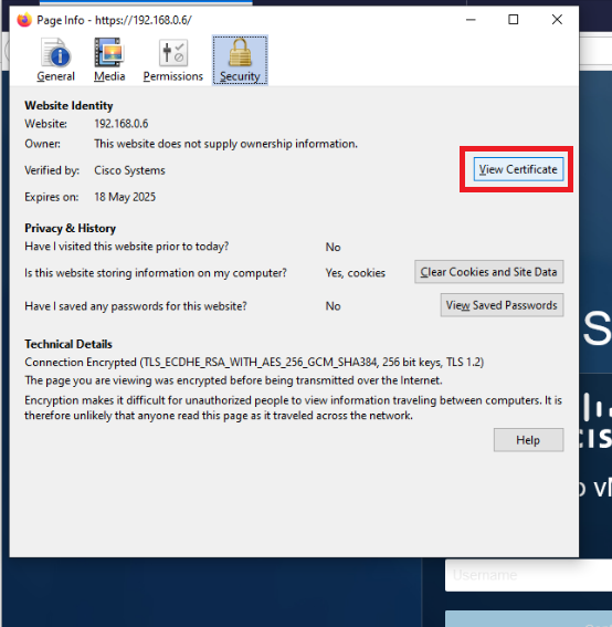
Open Firefox and navigate to the vManage GUI (https://192.168.0.6). We are using Firefox over here since the vManage web certs need to be downloaded. Accept any warnings that you receive
-
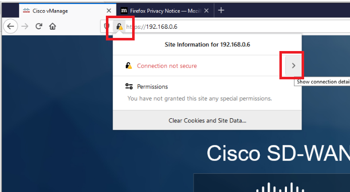
Click on the lock icon in the address bar and expand Connection not secure
-
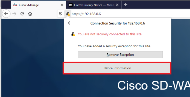
Click on More Information
-
Click on View Certificate
-
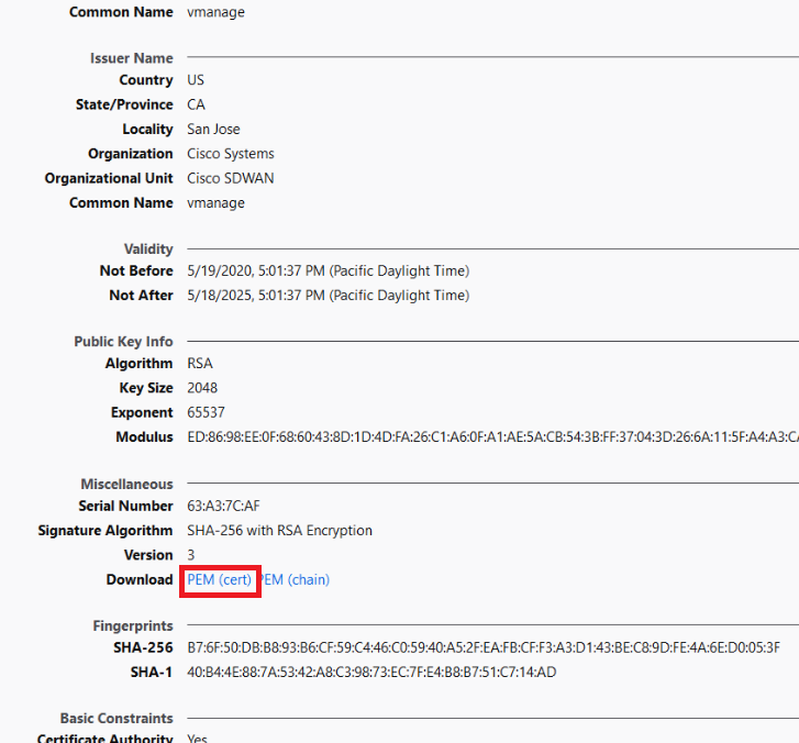
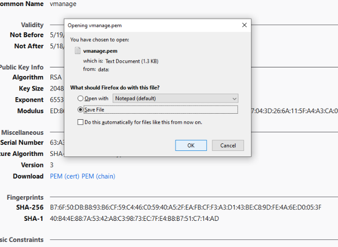
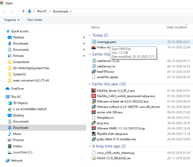
Click on PEM (cert) to download the vmanage.pem certificate. Choose to Save the File to the default location, which is the Downloads folder
-
We will now enable NAT at the DC site so that the WCM and vManage can communicate with each other. Log in to the vManage GUI (can use Chrome or Firefox now) and navigate to Configuration => Templates => Feature Tab and filter the results by typing DC-vEdge in the search bar
Username Password admin admin 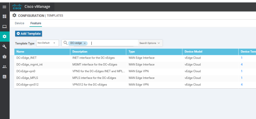
-
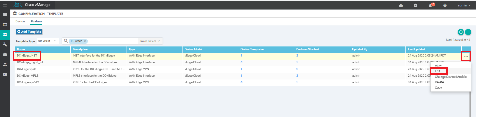
Locate the DC-vEdge_INET Feature Template and click on the three dots next to it. Choose to Edit the template
-
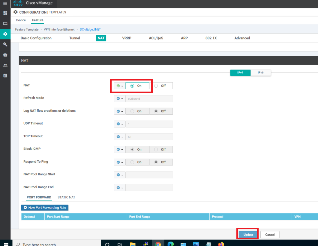
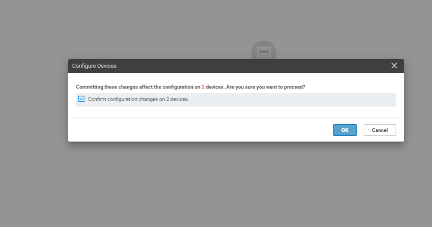
Scroll down to the NAT section and set it to a Global value of On. Click on Update
-
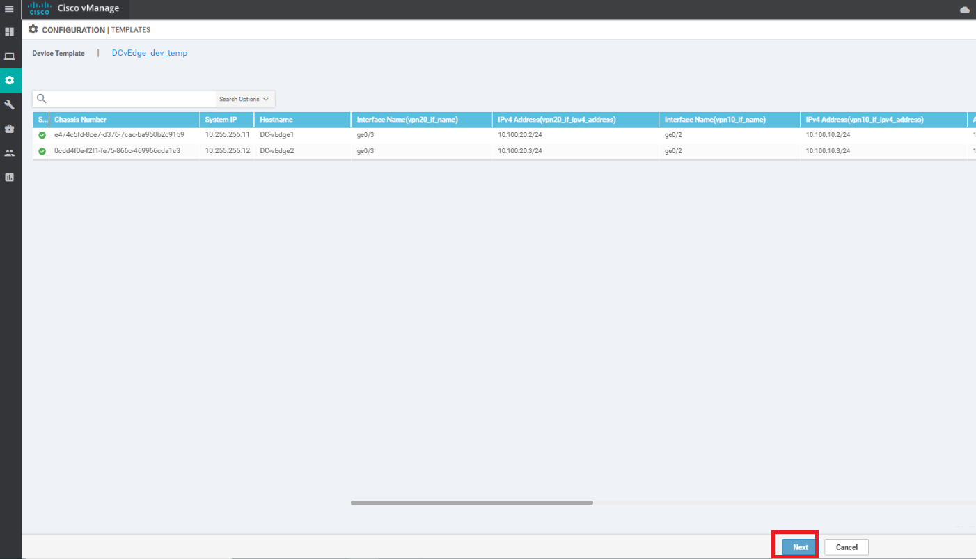
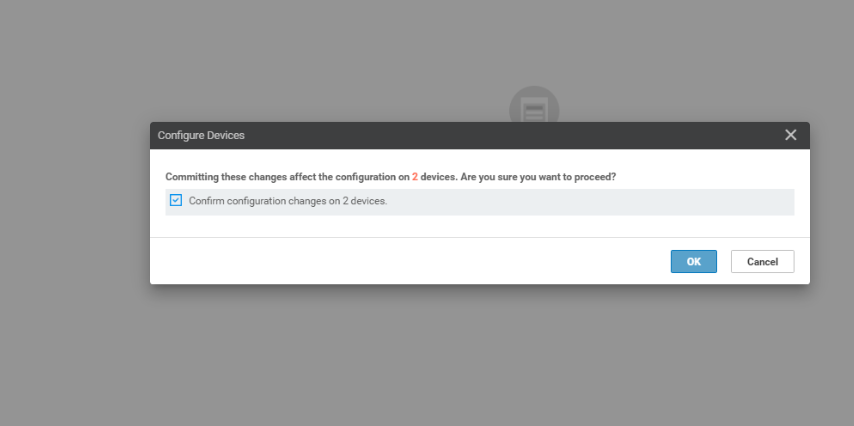
Click on Next, click on Configure Devices, confirm the change and click on OK
-
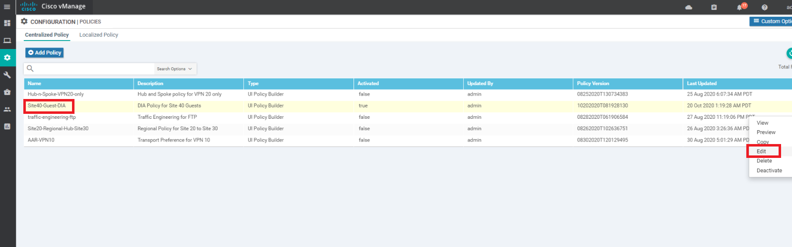
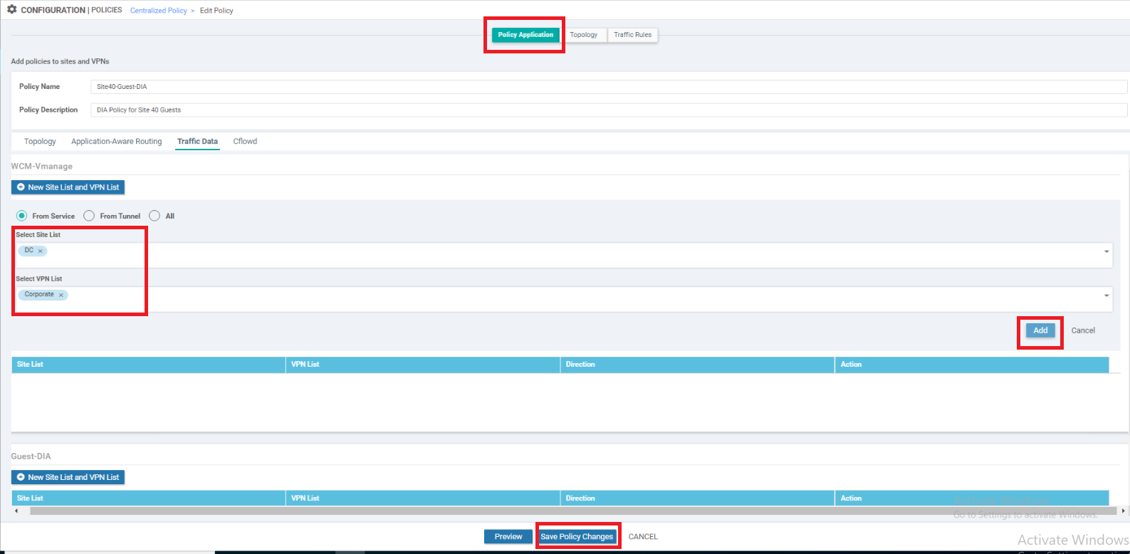
Click on Configuration => Policies and locate the Site40-Guest-DIA policy. Click on the three dots next to it and choose to Edit the policy. If the policy isn’t active, first activate the policy and then Edit
-
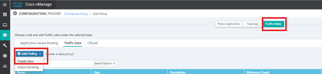
Click on the Traffic Rules tab and navigate to the Traffic Data sub-tab. Click on Add Policy and choose Create New
-
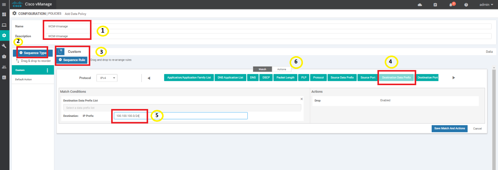
Enter a name and description of WCM-vManage. Click on Sequence Type and choose Custom. Click on Sequence Rule and select Destination Data Prefix under Match. Enter a Destination: IP Prefix of 100.100.100.0/24 and click on Actions
-
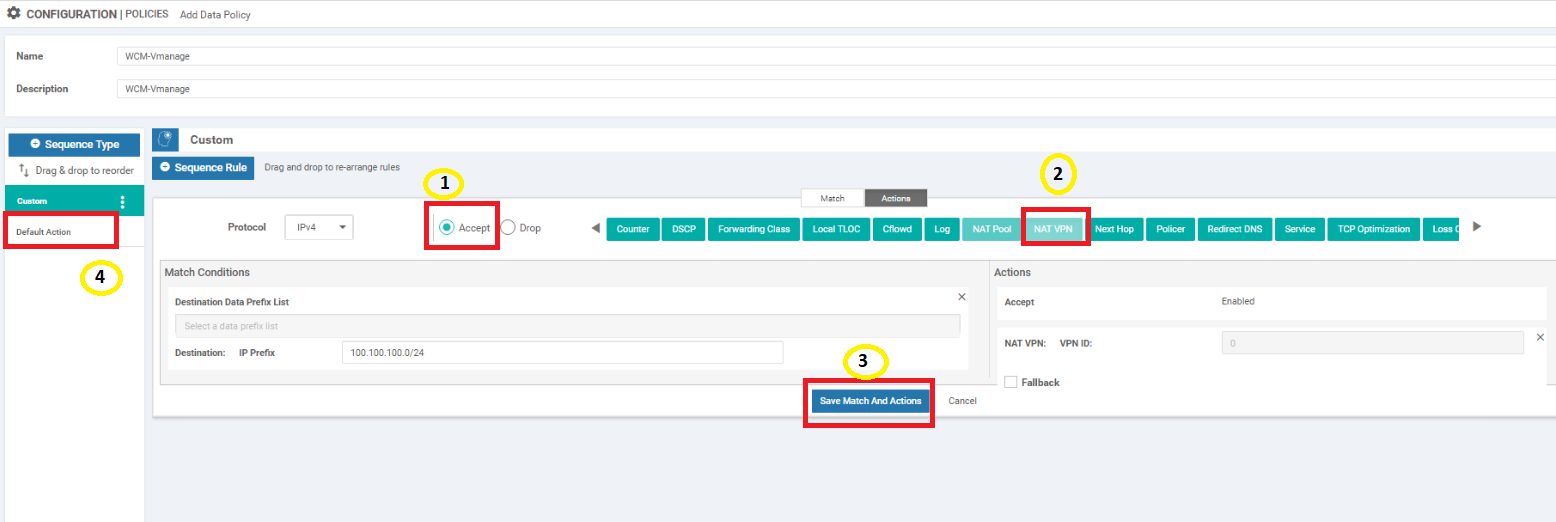
On the Actions tab, click on the Accept radio button and choose NAT VPN. Click on Save Match and Actions. Once saved, click on Default Action on the left hand side
-
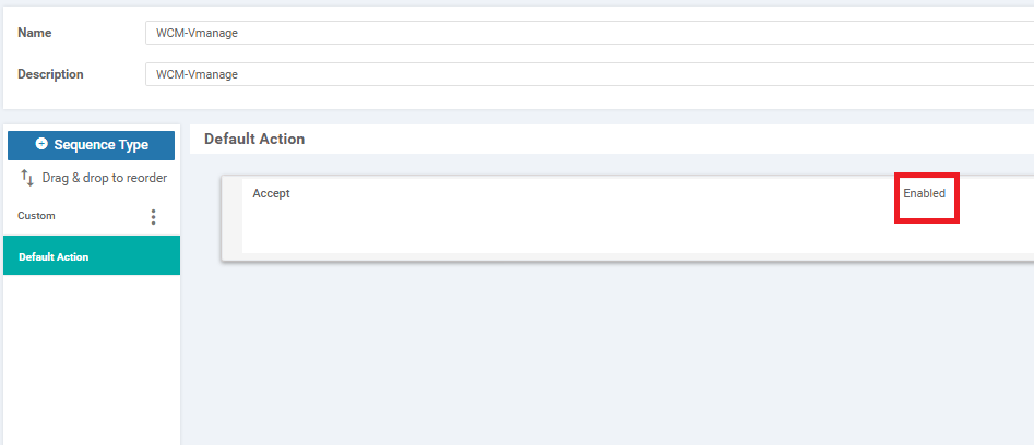
Edit the default action by clicking on the pencil icon and choosing Accept to be enabled. Click on Save to ensure that the default action is saved and then save the policy as well
-
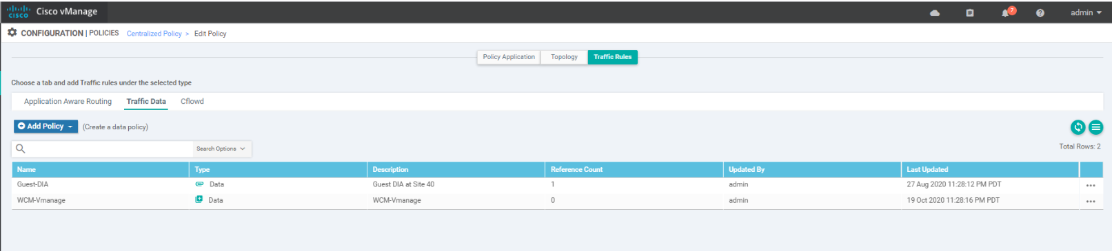
Once the policy is saved, you should see a new Data Policy called WCM-vManage
-
Click on the Policy Application tab and then click on the Traffic Data sub tab. Under the WCM-vManage policy, click on New Site List and VPN List. Leave the direction as From Service and choose DC under Select Site List. Choose Corporate under Select VPN List. Click on Add and then click on Save Policy Changes. Choose to Activate if prompted
-
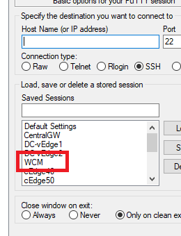
Once the policy is updated successfully, open Putty and log in to the CLI of WCM (10.100.10.100 or use the saved session). Ping the following destinations to ensure connectivity
- 100.100.100.2
- 10.40.10.2
- 10.50.10.2 and 10.50.10.3
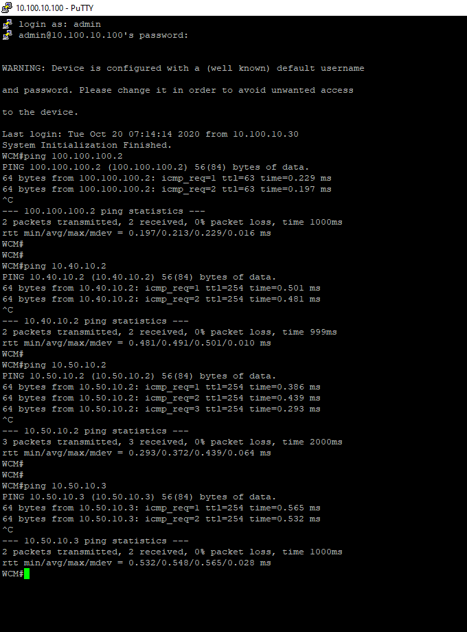
ping 100.100.100.2 ping 10.40.10.2 ping 10.50.10.2 ping 10.50.10.3 - 100.100.100.2
We have completed configuration needed for ensuring WCM can talk to vManage. We have also downloaded the vManage web cert which will be required for the integration.
-
-
-
- Integrating vManage and WCM
- Discovering the AppNav-XE Controllers
- Setting up the AppNav Clusters
- Verification and Testing
Integrating vManage and WCM
-
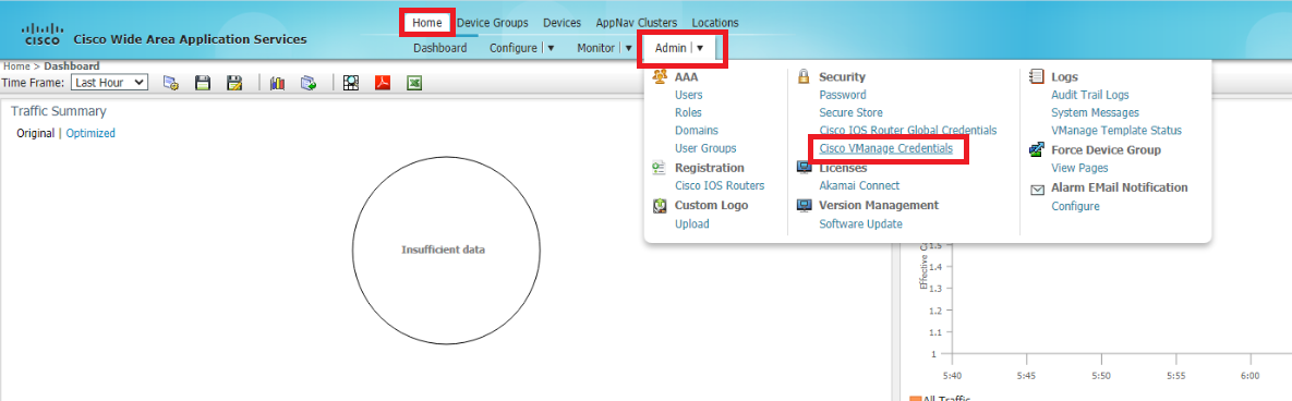
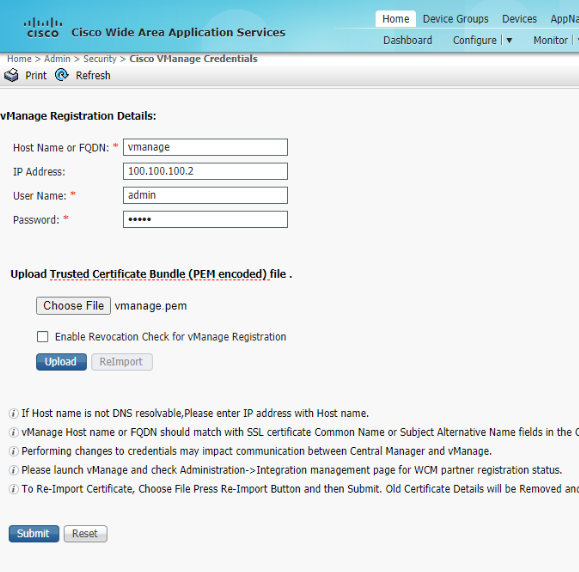
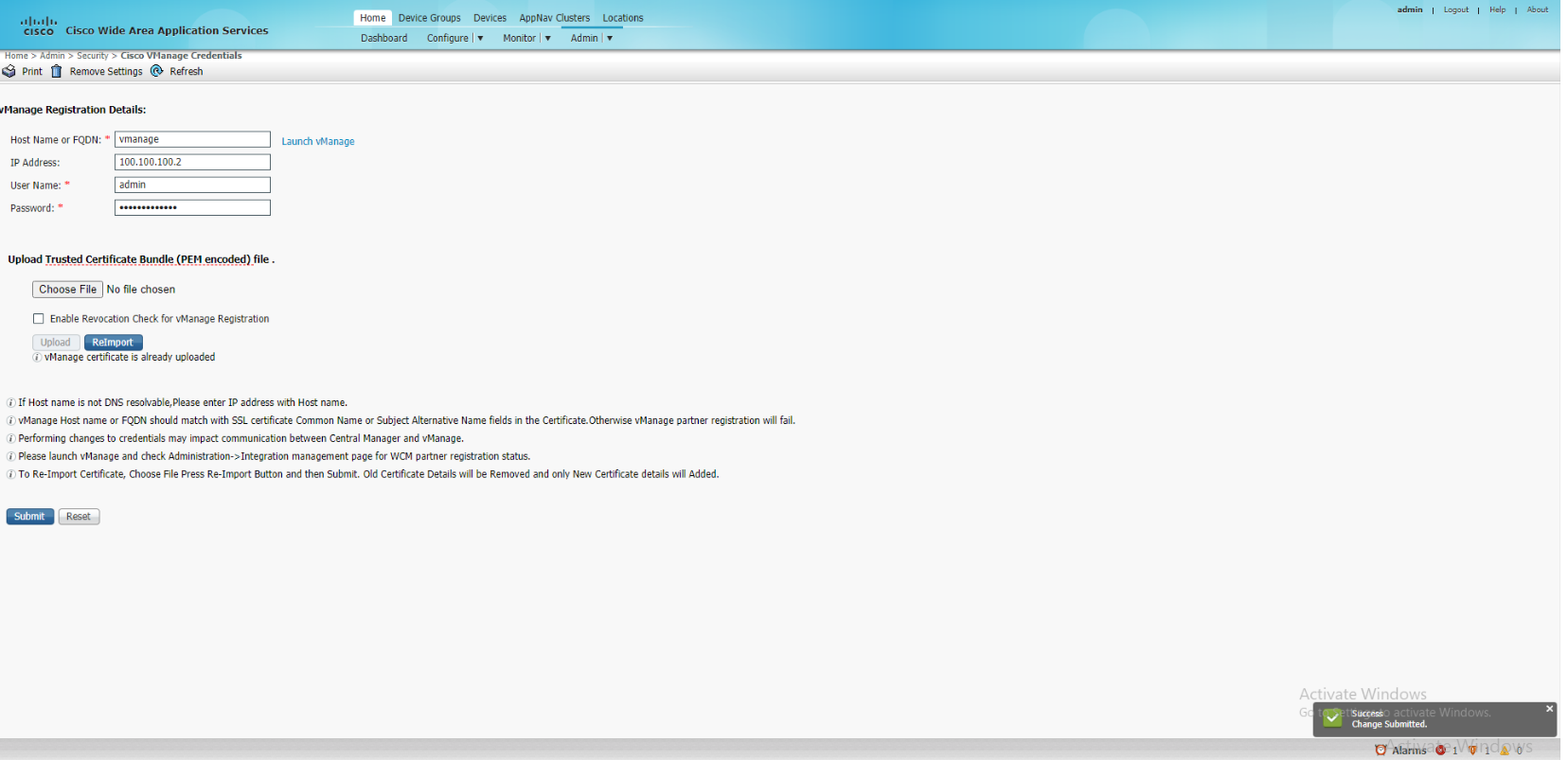
Log in to WCM and make sure you’re on the Home tab. Under Admin, click on Cisco vManage Credentials
-
Enter the details of vManage as enumerated below and click on Choose File. Select the vmanage.pem certificate downloaded before in the Downloads folder and click on Upload
Hostname or FQDN IP Address Username Password vmanage 100.100.100.2 admin admin 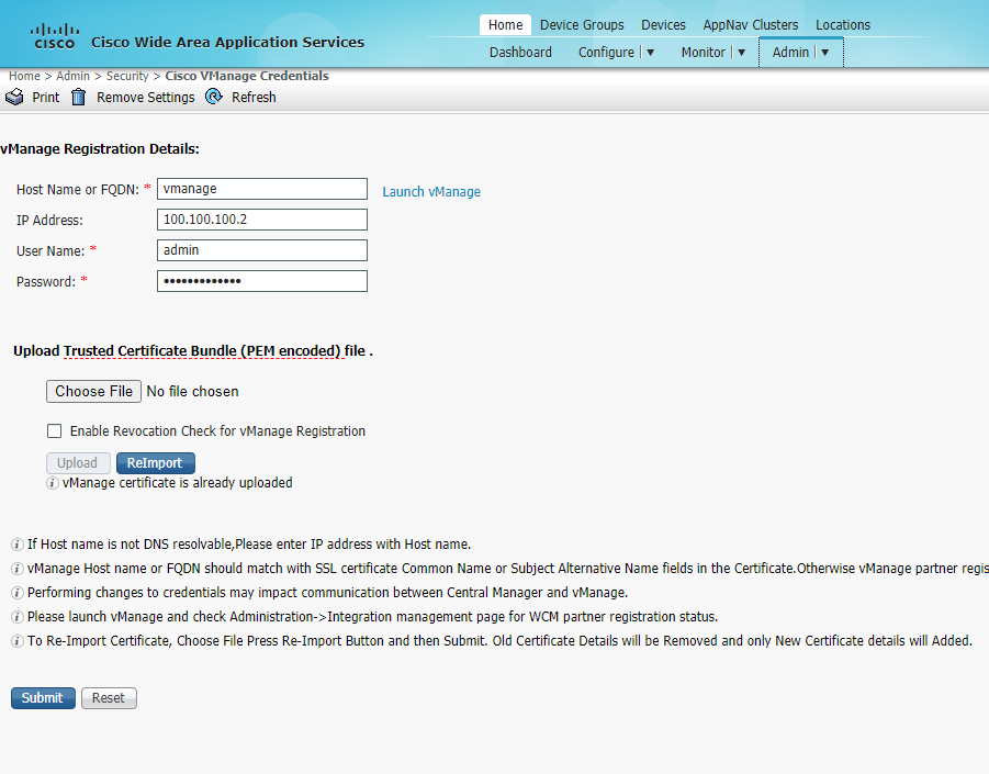
-
Once the certificate has been uploaded successfully, click on Submit. You should see a notification in the bottom right hand corner indicating that the changes were submitted successfully
-
Back at the vManage GUI, navigate to Administration => Integration Management. The WCM should show up over here
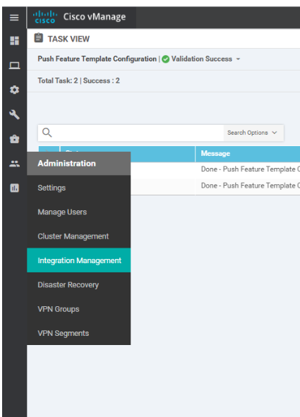
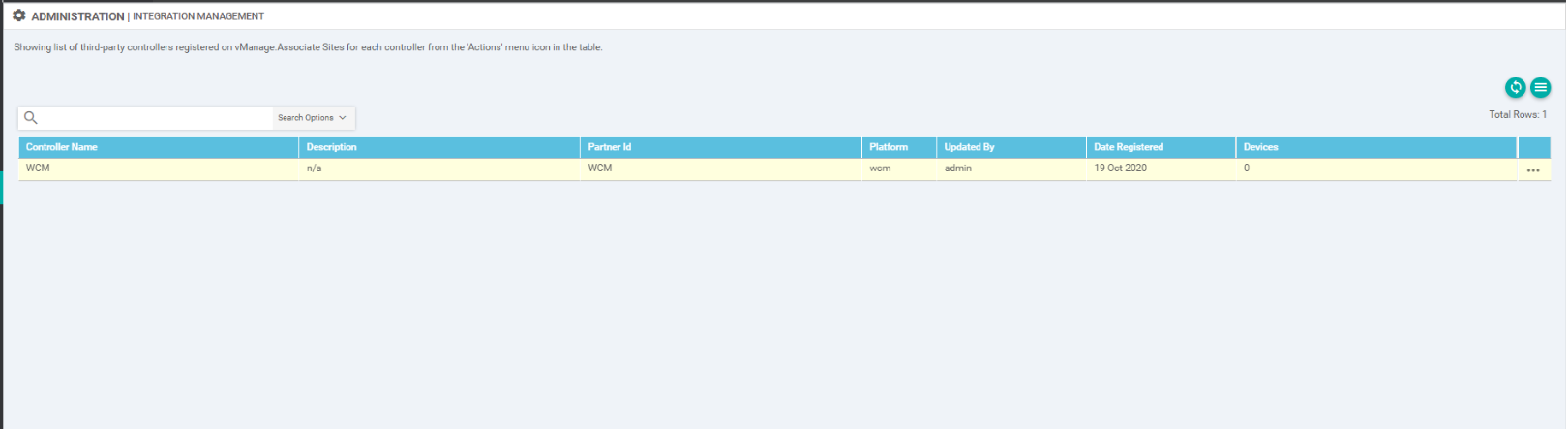
At this point, WCM and vManage have been integrated. We will now prep the cEdges so that they can be discovered by WCM as AppNav-XE Controllers.
-
-
-
-
- Discovering the AppNav-XE Controllers
- Setting up the AppNav Clusters
- Verification and Testing
Discovering the AppNav-XE Controllers
Before the WAN Edge devices can be discovered as AppNav-XE Controllers, we will need to make some changes on them.
-
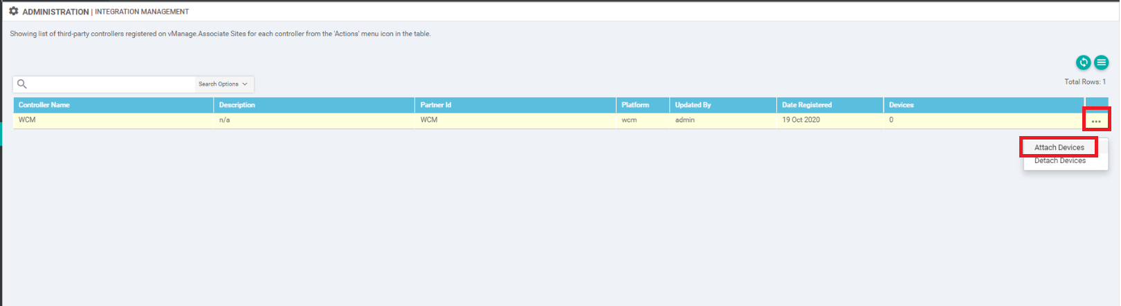
On the Administration => Integration Management page of vManage, click on the three dots next to the WCM entry and click on Attach Devices
-
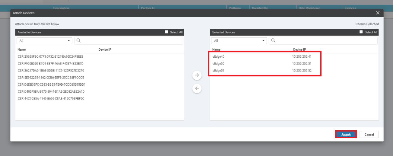
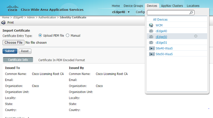
Select cEdge40, cEdge50 and cEdge51 and move them over to the right hand side. Click on Attach. You should now see 3 devices attached to WCM
-
Go to Configuration => Templates => Feature Tab and click on Add Template. Search for and select the CSR100v and click on Global Settings
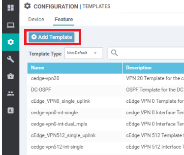
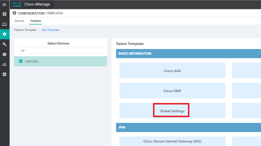
-
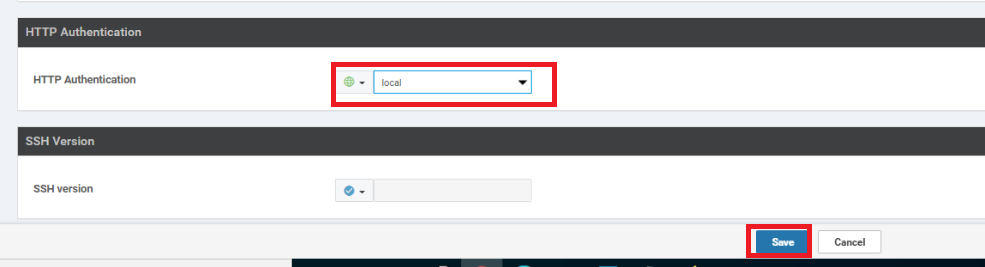
Enter the following details for the Template and click on Save
Section Field Global or Device Specific (drop down) Value Template Name HTTP-HTTPS-WCM Description HTTP-HTTPS-WCM Services HTTP Server Global On Services HTTPS Server Global On HTTP Authentication HTTP Authentication Global local 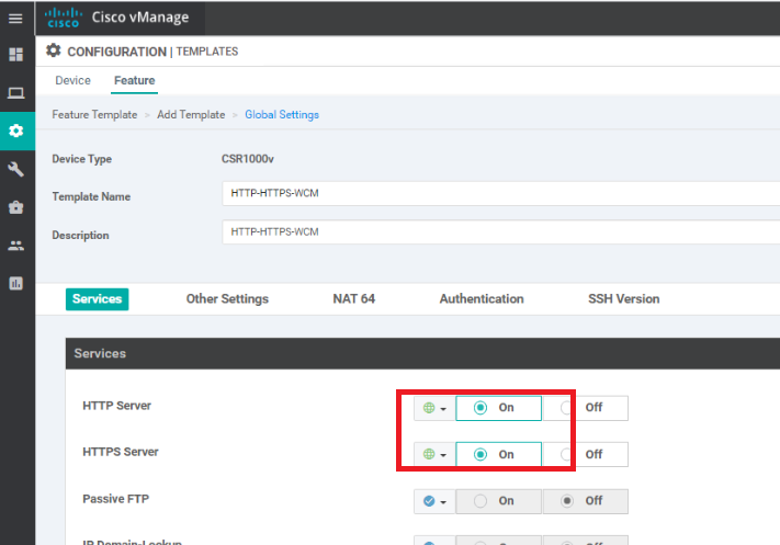
-
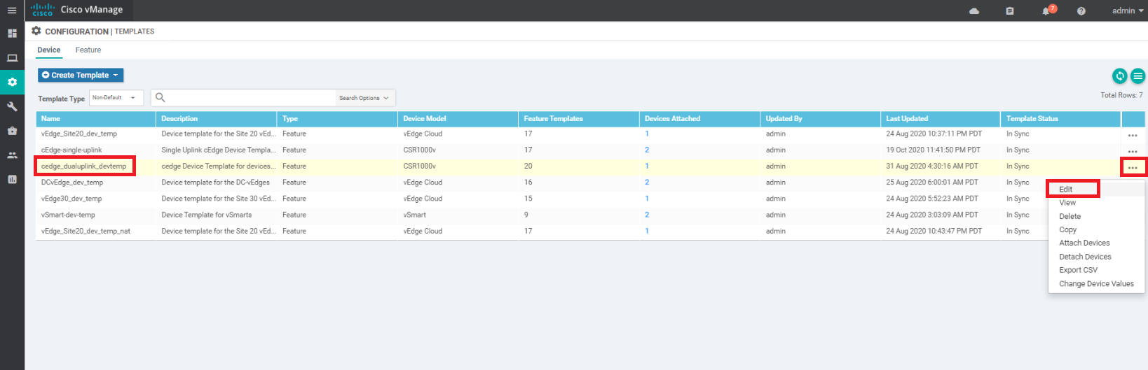
We will now associate this template to the cEdges that will be functioning as AppNav-XE Controllers. Navigate to Configuration => Templates. Locate the cEdge-single-uplink template and click on the three dots next to it. Choose to Edit the template
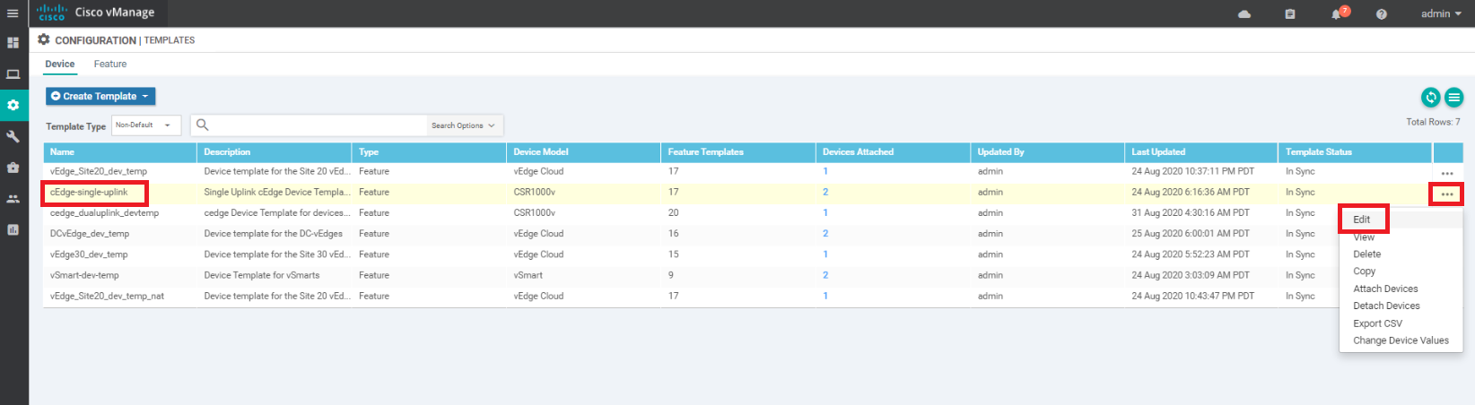
-
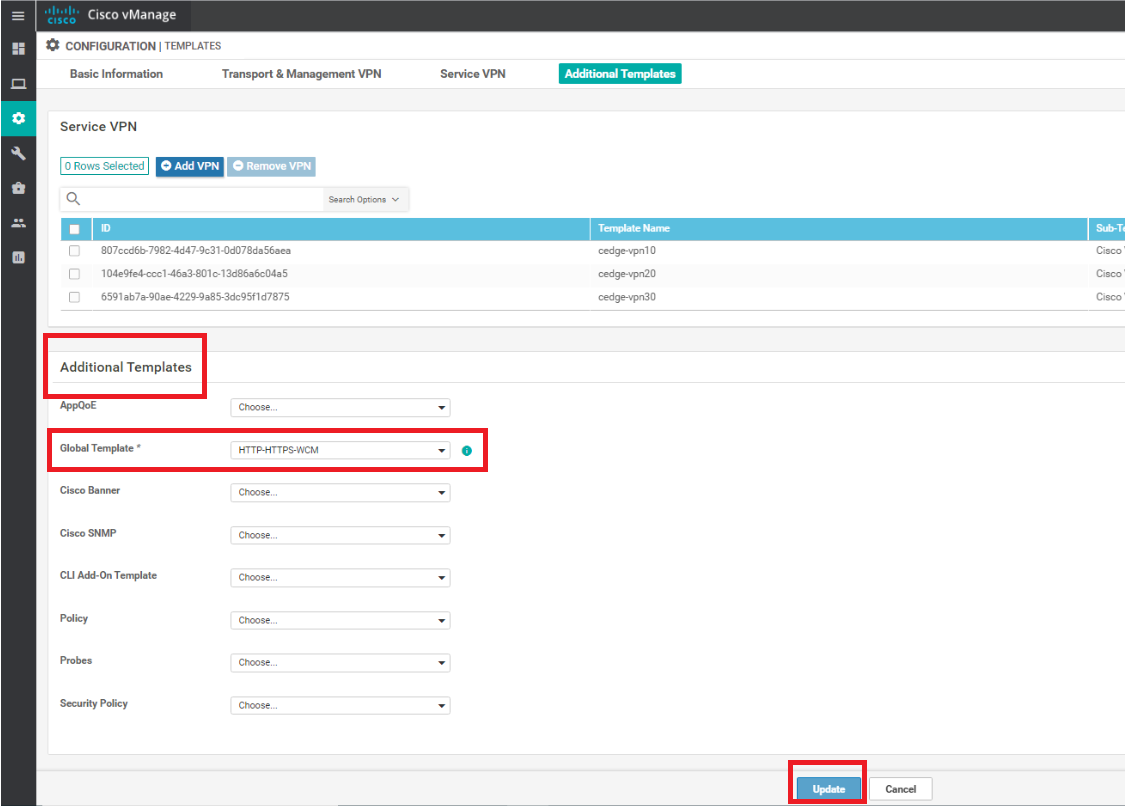
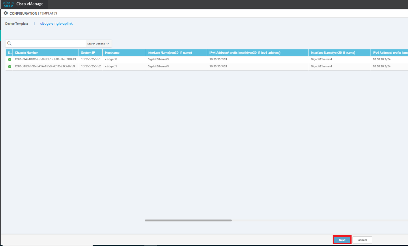
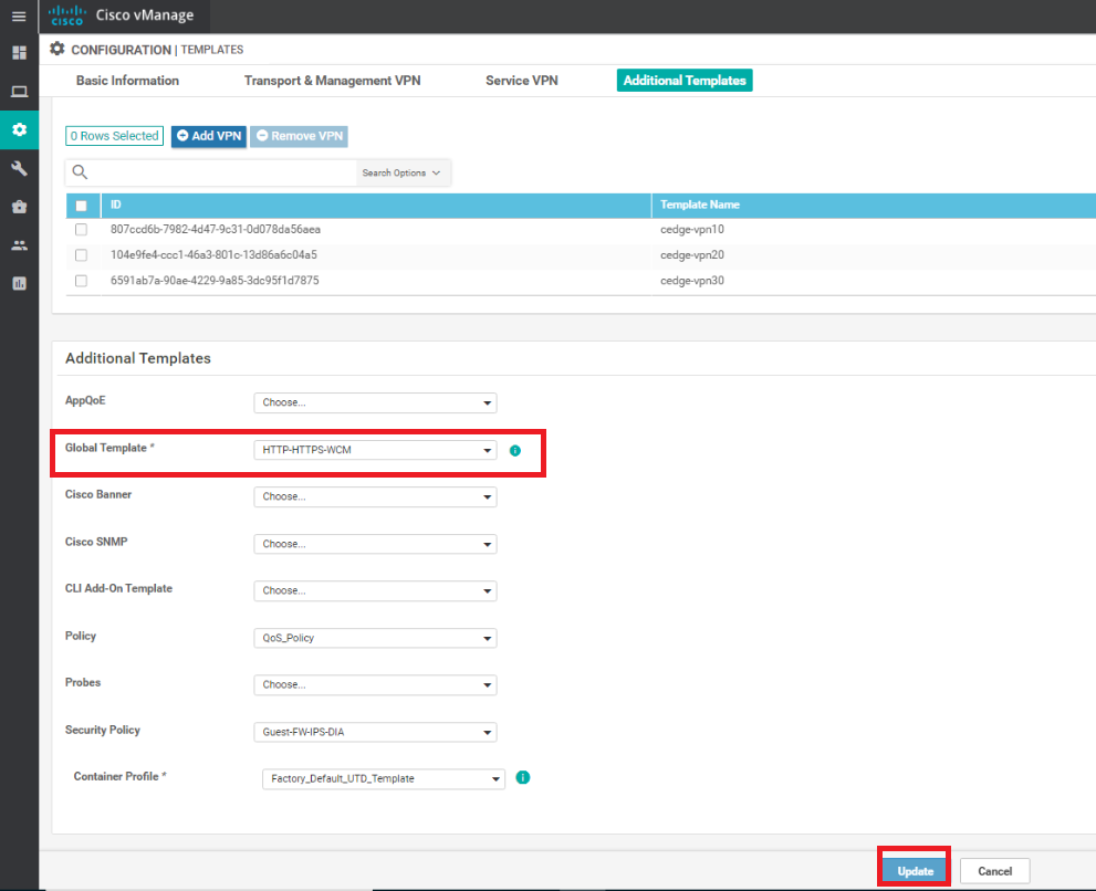
Under Additional Templates, set the Global Template to the HTTP-HTTPS-WCM template we just created and click and Update. Click on Next and Configure Devices, confirming the configuration change on two devices
-
Repeat the procedure of updating the Global Template for the cedge_dualuplink_devtemp Device Template
-
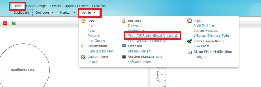
On the WCM GUI, make sure you’re on the Home tab and click on Cisco IOS Global Router Credentials under Admin
-
Enter the username and password of the WAN Edges and click on Submit
Username Password admin admin 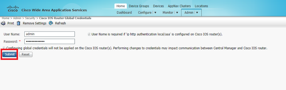
-
Again under Admin, go to Cisco IOS Routers
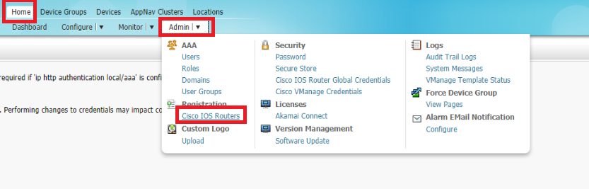
-
Enter the IP Addresses of your WAN Edges and feed in the username/password of the devices. Set the Authentication to local and enter the WCM IP of 10.100.10.100 and click on Register. The IP Addresses should be enetered as 10.40.10.2, 10.50.10.2, 10.50.10.3
Username Password admin admin 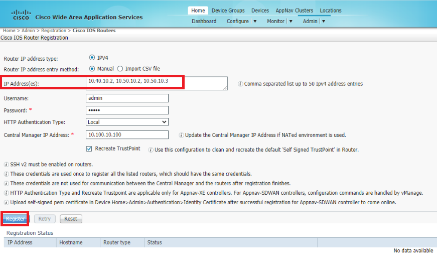
-
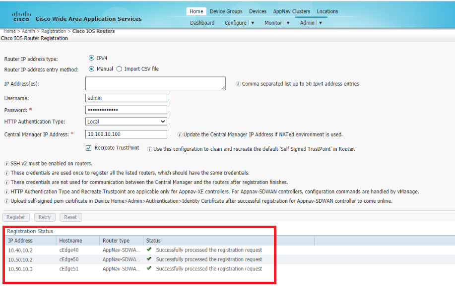
You should see the Registration status update in the lower half of the screen. If it doesn’t show the WAN Edges, refresh the page. The WAN Edges should register successfully
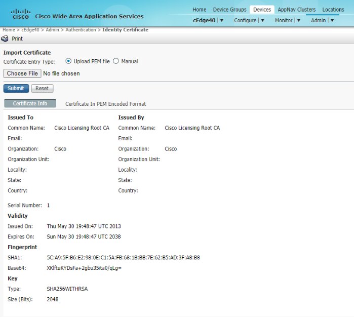
- In order to complete the registration, we will need to upload the certificate of each device on WCM. Log in to the CLI of cEdge40 via Putty and issue the command
show crypto pki certificate pem. Copy the certificate and paste it in Notepad. Make sure there aren’t any additional characters at the end (sometimes, a new line is copied as well and this can cause issues while pasting the certificate)show crypto pki certificate pemUsername Password admin admin 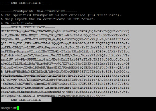
-
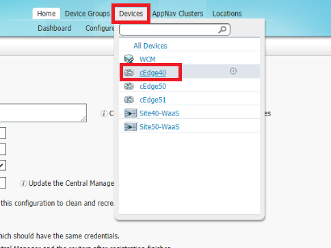
On the WCM GUI, go to Devices => cEdge40. Once on the cEdge40 page, click on Admin => Identity Certificate
-
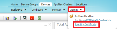
Select the Certificate Entry Type as Manual and paste the certificate we just copied in the box. Click on Submit. If you look at the certificate info tab, the contents of the certificate should be visible
-
Repeat steps 13 till 15 for cEdge50 and cEdge51, copying their respective certificates to the WCM GUI
This completes the discovery and registration of the AppNav-XE Controllers to WCM.
-
-
-
-
-
- Setting up the AppNav Clusters
- Verification and Testing
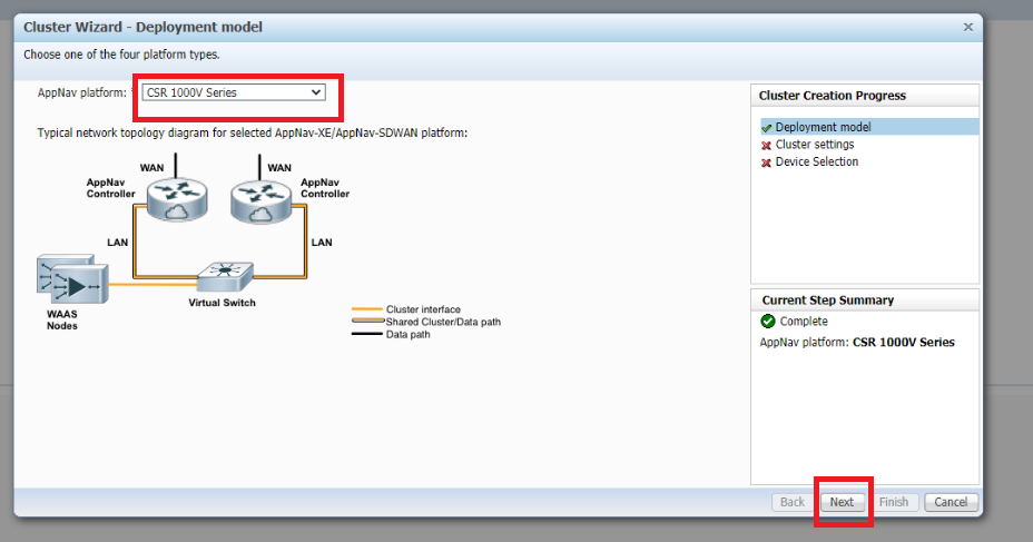
Setting up the AppNav Clusters
We will be setting up two AppNav Clusters in the lab. One will be at Site 40 and another at Site 50.
-
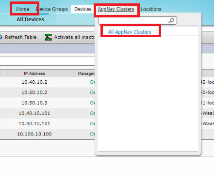
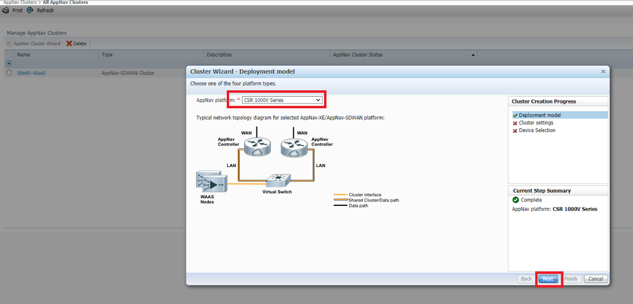
On the WCM GUI, make sure you’re at the Home tab and click on Appnav Clusters. Choose All AppNav Clusters
-
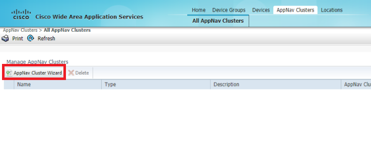
Click on AppNav Cluster Wizard to start setting up our AppNav clusters
-
Choose CSR 1000V Series for the AppNav Platform since we will be using the CSRs at Site 40 and Site 50 as the AppNav-XE controllers. Click on Next
-
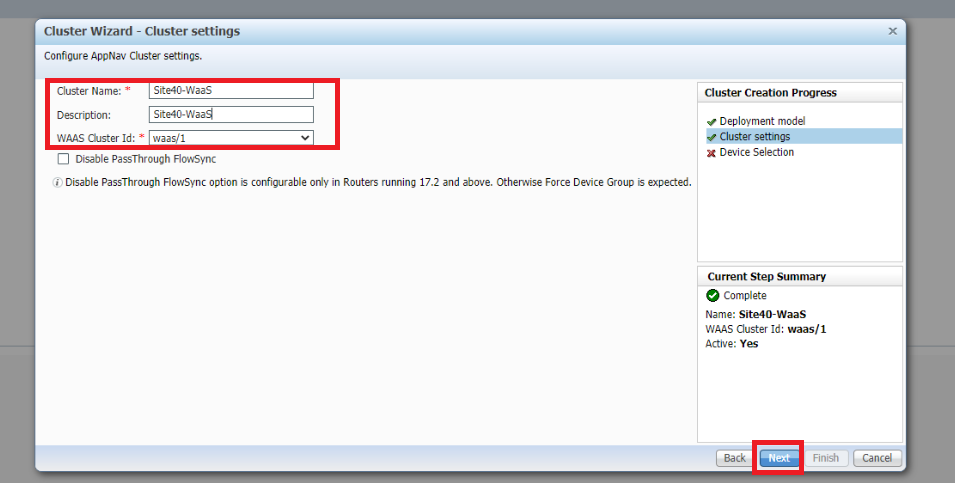
Enter a Cluster Name and Description of Site40-WaaS, select the WAAS Cluster ID as waas/1 and click on Next
-
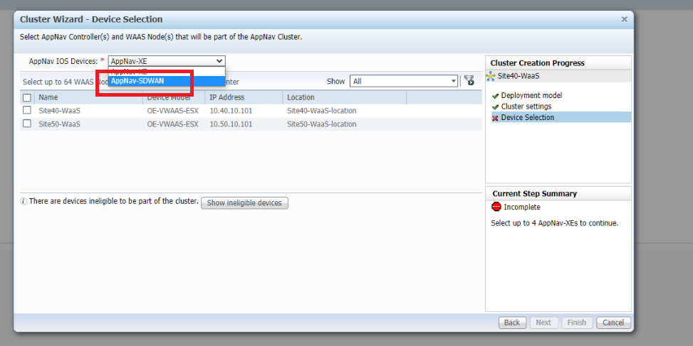
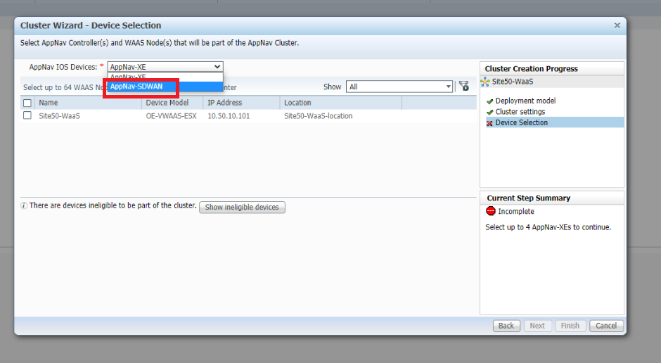
Select the AppNav IOS Devices as AppNav-SDWAN
-
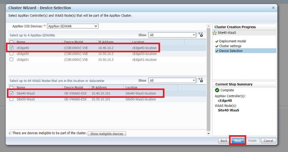
Select cEdge40 in the upper half of the window and Site40-WaaS in the lower half. We’re choosing the components of our cluster over here. Click on Next
-
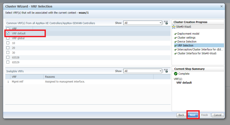
Select VRF default and click on Next. This associates all VRFs with the context waas/1
-
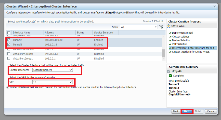
Select Tunnel2 and Tunnel3 as the WAN interfaces on which data path interception should be enabled. Make sure the Cluster Interface is set to GigabitEthernet4 and the VRF is 10. Click on *Next
-
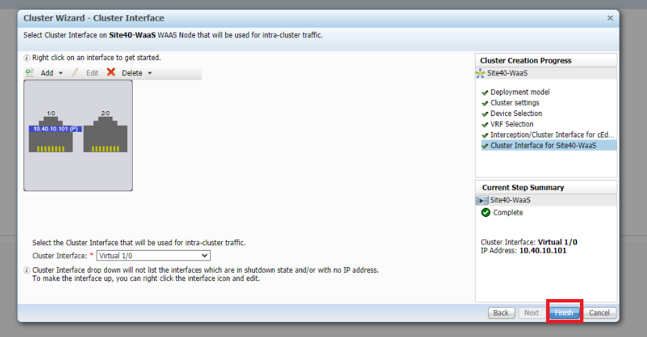
Click on Finish, making sure the cluster interface is set to Virtual 1/0
-
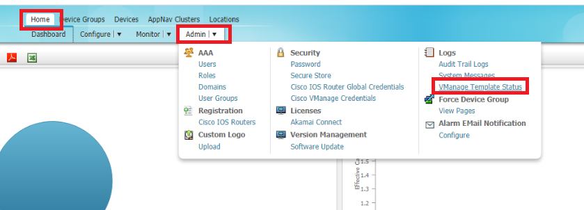
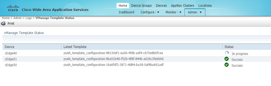
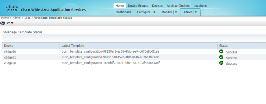
Templates are pushed to vManage which in turn configures the AppNav-XE Controllers. The status of the template push can be checked on vManage or on WCM. On WCM, make sure you’re on the Home tab and click on vManage Template Status under Admin. Wait for the templates to get deployed before proceeding
-
We have built our AppNav Cluster at Site 40. A similar procedure will need to be followed for the Site 50 AppNav Cluster. Open the AppNav Cluster Wizard and select the AppNav Platform as CSR 1000V Series. Click on Next
-
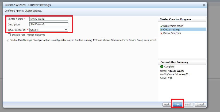
Enter a Cluster Name and Description of Site50-WaaS, select the WAAS Cluster ID as waas/2 and click on Next
-
Select the AppNav IOS Devices as AppNav-SDWAN
-
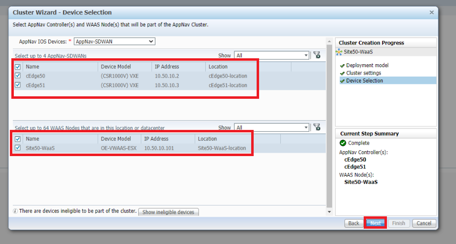
Select cEdge50 and cEdge51 in the upper half of the window and Site50-WaaS in the lower half. We’re choosing the components of our cluster over here. Click on Next
-
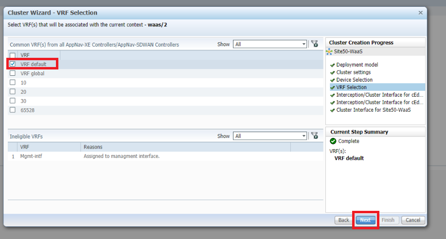
Select VRF default and click on Next. This associates all VRFs with the context waas/2
-
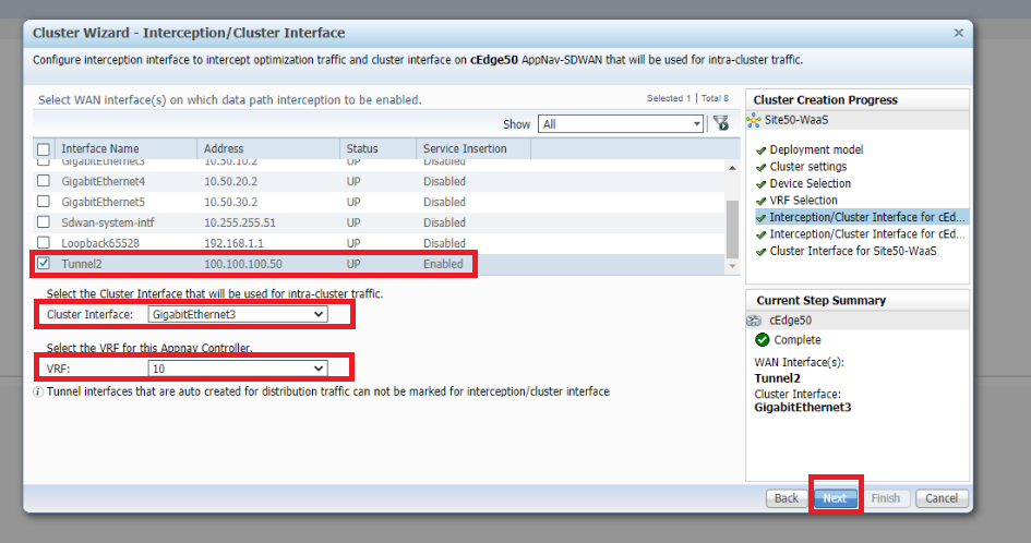
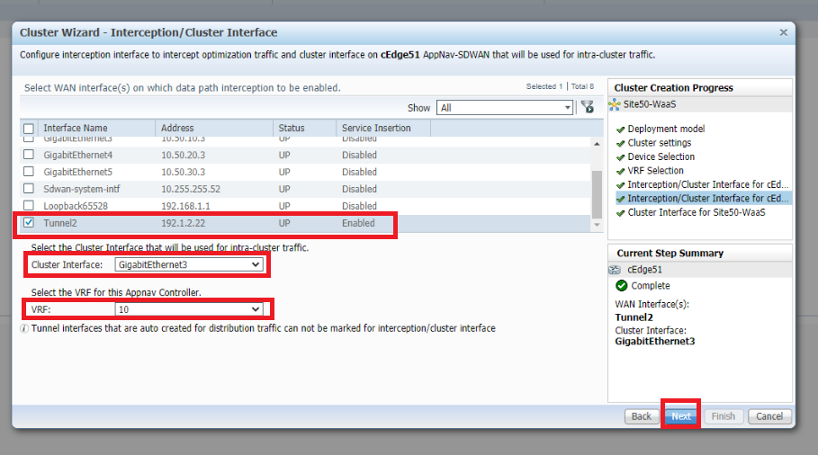
Select Tunnel2 as the WAN interfaces on which data path interception should be enabled. Make sure the Cluster Interface is set to GigabitEthernet3 and the VRF is 10. Click on Next. This is for cEdge50
-
Select Tunnel2 as the WAN interfaces on which data path interception should be enabled. Make sure the Cluster Interface is set to GigabitEthernet3 and the VRF is 10. Click on Next. This is for cEdge51
-
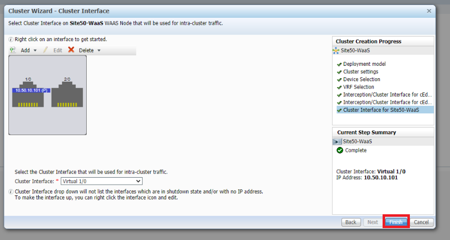
Click on Finish, making sure the cluster interface is set to Virtual 1/0
-
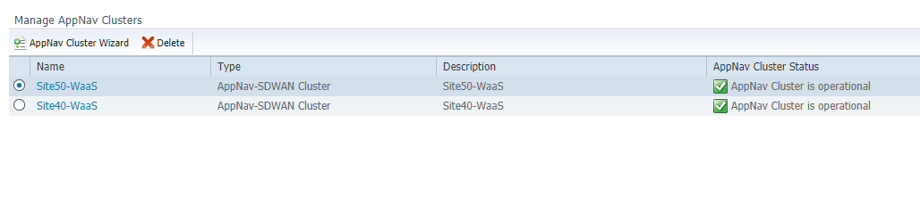
Wait for approximately 8 minutes and head over to the AppNav Cluster section on WCM, clicking on All AppNav Clusters. Both clusters we just created should be operational
We have created the AppNav Clusters and applied some default policies. Traffic optimization should be in effect. This will be verified in the next section.
-
-
-
-
-
-
- Verification and Testing
Verification and Testing
We will be testing things out in VPN 10 and generating HTTP traffic in that VPN from Site 40 to Site 50. A few changes will need to be made on the workstations available at Site 40 and Site 50, post which we can begin verification.
-
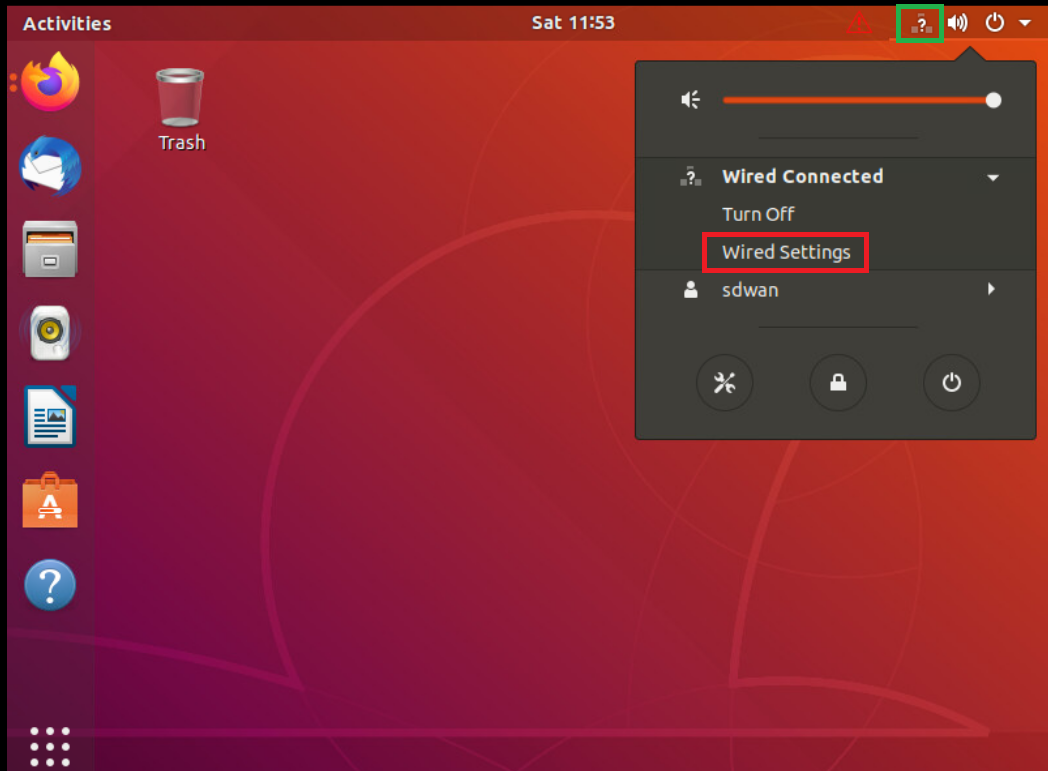
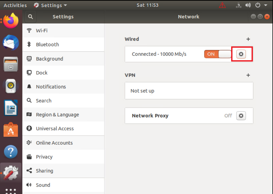
Log in to vCenter (use the bookmark or go to 10.2.1.50/ui if connected to the GHI DC and 10.1.1.50/ui if connected to the SJC DC) using the credentials provided to you. Locate the sdwan-sjc/ghi-site40pc-podX VM and click on it. Open the Web Console to the Site 40 PC VM and log in. The Username is sdwan and the password is C1sco12345. Click the network icon in the top-right corner and go to Wired Settings
-
Click on the cog wheel/gear icon
-
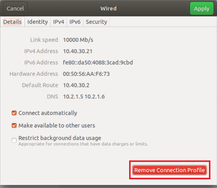
Click on Remove Connection Profile
-
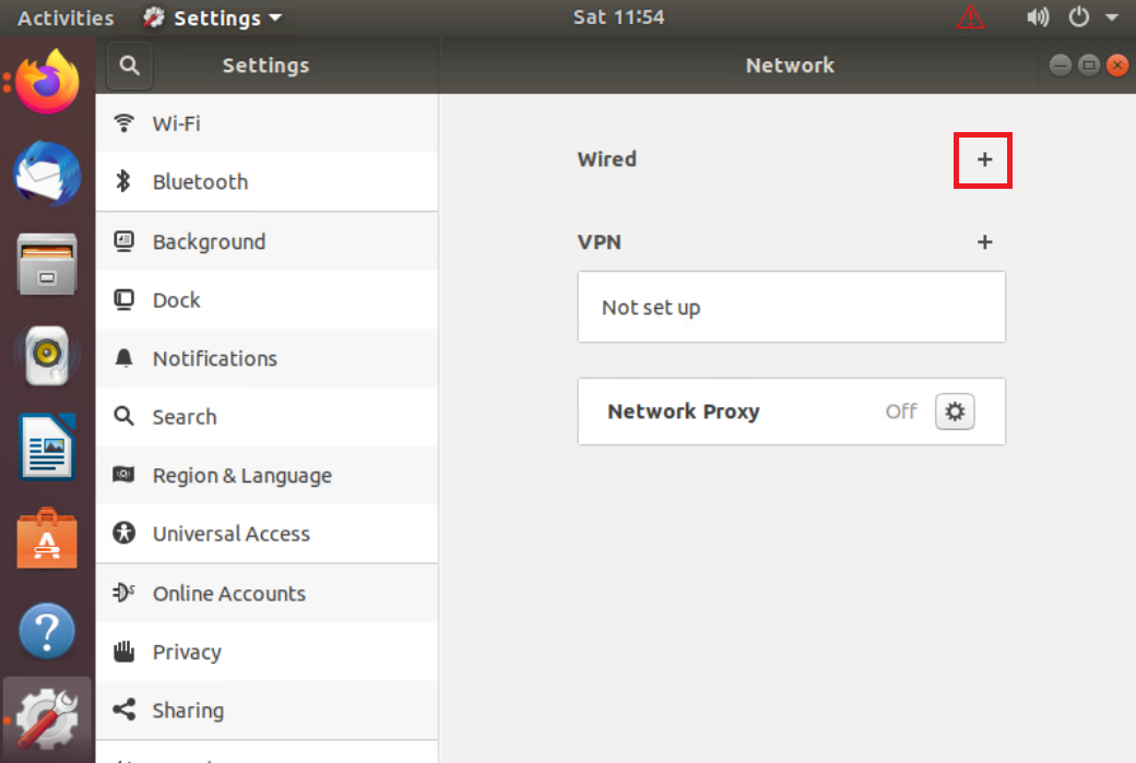
The + sign should show up next to Wired. If you still see a cog wheel/gear icon, click on it and choose Remove Connection Profile again. Once the + icon is visible, click on it
-
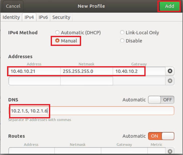
Go to the IPv4 tab and set the IPv4 Method as Manual. Enter the following details and click on Add
Address Netmask Gateway DNS 10.40.10.21 255.255.255.0 10.40.10.2 Automatic - Off
10.y.1.5, 10.y.1.6Over here, y is 1 if you’re on the SJC DC and 2 if you’re on the GHI DC (the email with lab details should enumerate which DC you’re on).
-
Back at the vCenter screen, right click on the Site40PC (named sdwan-sjc/ghi-site40pc-podX) for your POD and click on Edit Settings (image as an example only)
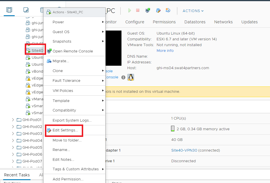
-
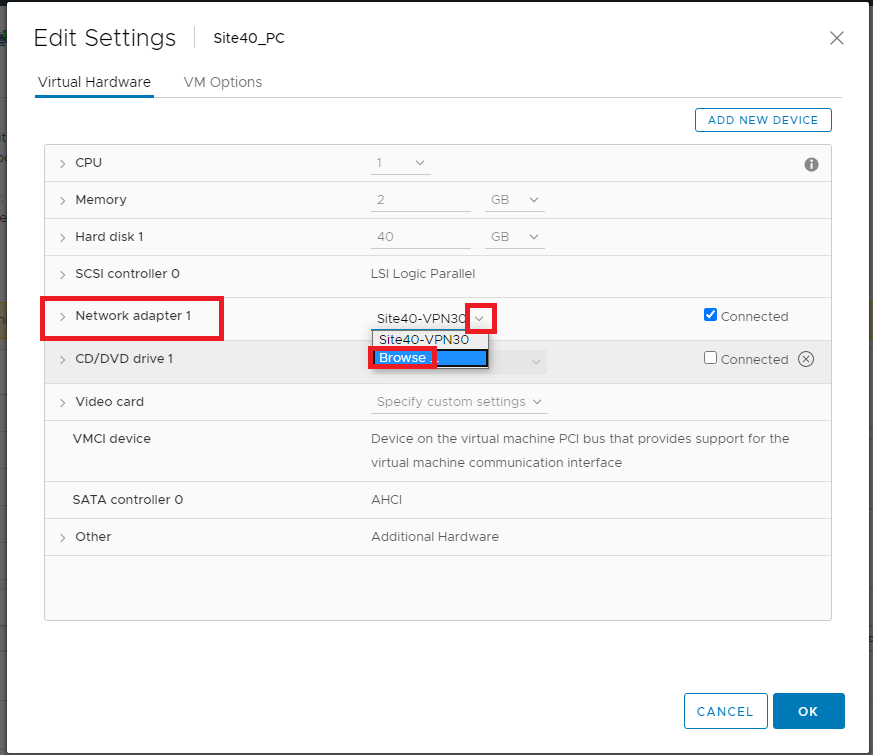
Under Network Adapter 1 click on the drop down and click Browse
-
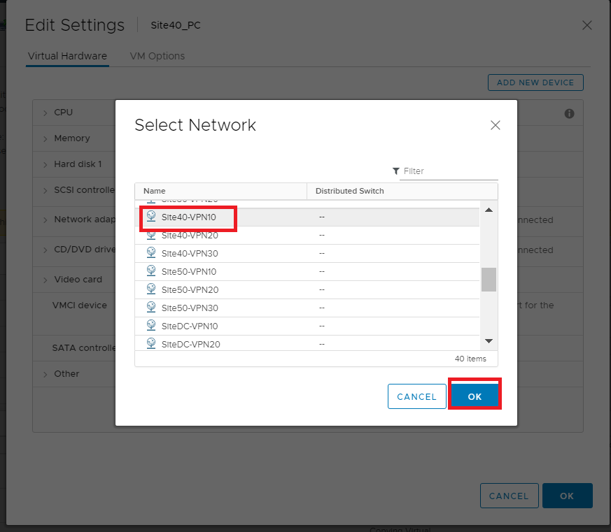
Select Site40-VPN10 from the list of Networks and click on OK. Click on OK again. The Site 40 PC is now in VPN 10
-
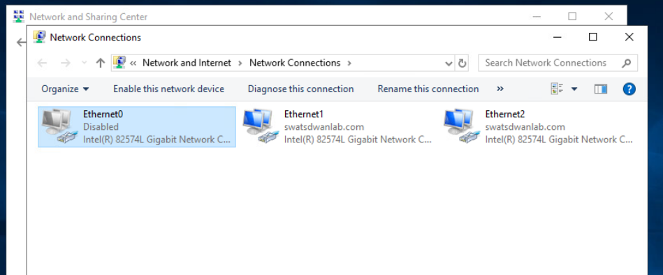
Back at vCenter, console in to sdwan-sjc/ghi-ad-podX. The username is administrator and the password is C1sco12345. Click on Start and type ncpa.cpl to open the Network Connections. Right click on Ethernet0 and Disable it. Right click on Ethernet2 and Enable the adapter
-
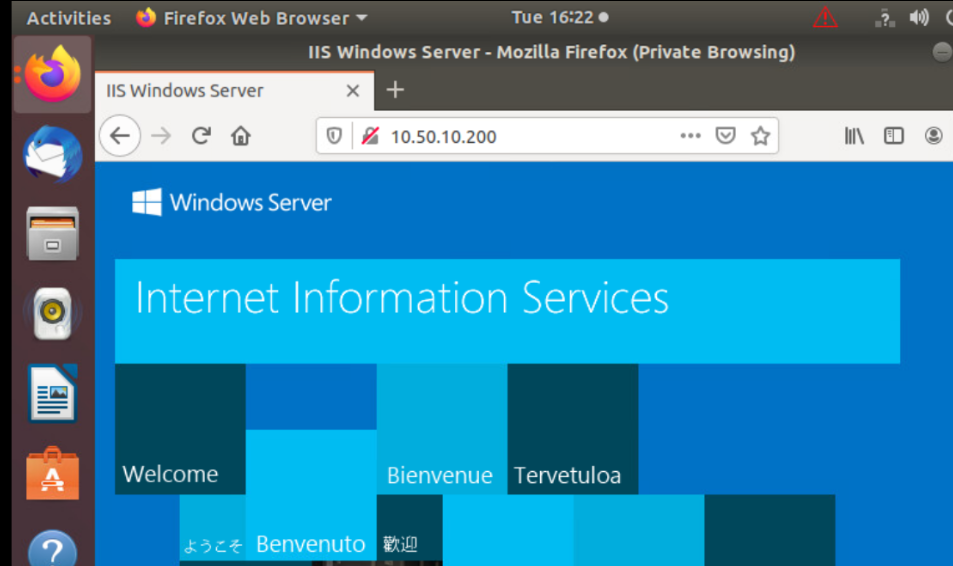
Go to the Site 40 PC console session and open Firefox. Access 10.50.10.200 via the browser - it should open an IIS page. Open multiple tabs to the same IP so as to generate some web traffic
-
SSH to the Site40-WaaS Node (IP of 10.40.10.101) or console in via vCenter (VM name is sdwan-sjc/ghi-site40waas-podX). Log in via the username of admin and a password of default and enter the command
show statistics connection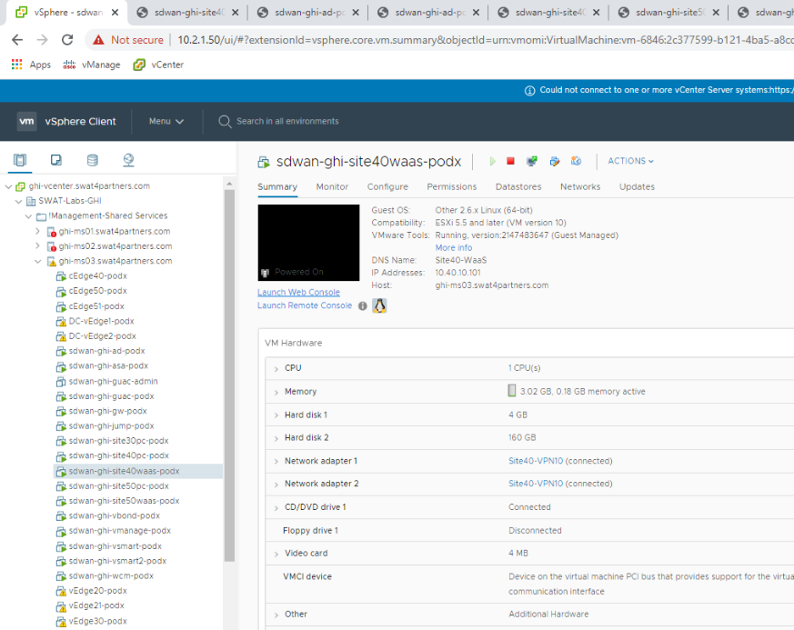
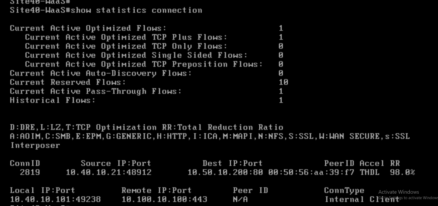
We can see that the web traffic is showing up in the output and it has a Reduction Ratio (RR) of 98% in this example. The RR will vary.
-
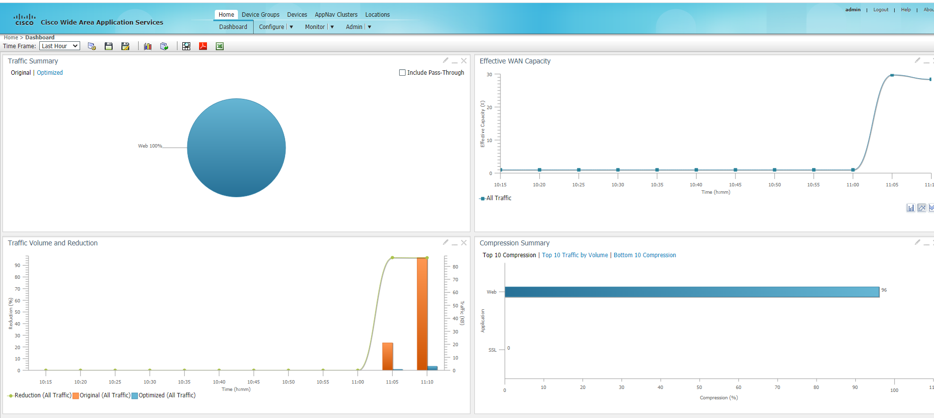
On the WCM GUI, navigate to the main dashboard by clicking on Home. You should see traffic being optimized
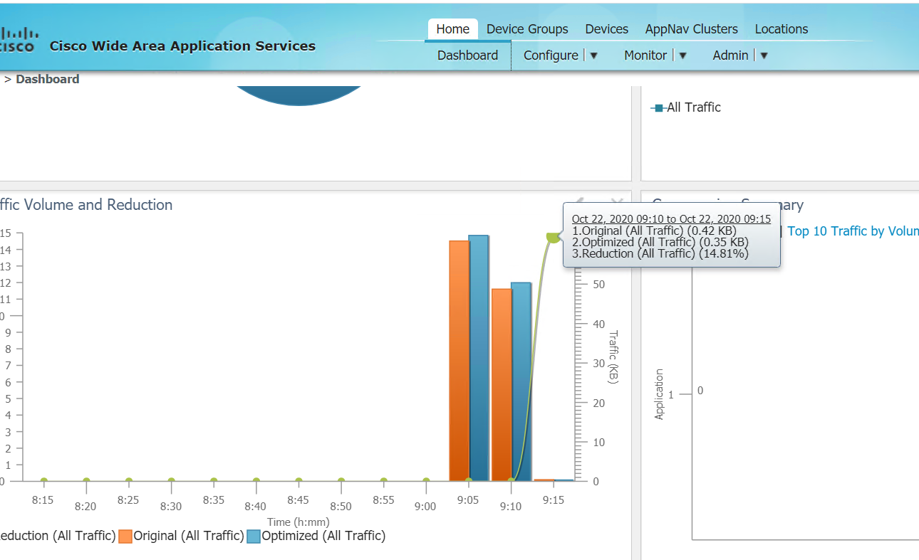
This completes the integration of WAAS with Cisco SD-WAN.