- Overview
- Feature Templates for TLOC Extensions
- Creating the VPN Interface Template for the TLOC-EXT interface
- Creating the VPN Interface Template for the Tunnel interface
- Creating the BGP Template for the MPLS link
- Updating the VPN and Device Templates
- Activity Verification
Overview
A number of sites have a couple of routers in place, but transport connectivity to just one of the available transports. In the event of a link failure, there is no mechanism for traffic to be redirected over the other transport. That’s where TLOC Extensions come in.
TLOC Extensions allow vEdge/cEdge routers with a single transport to utilize the link on another vEdge/cEdge router at the same site. Given below is a graphical representation of what we’re trying to achieve in this section of the lab.
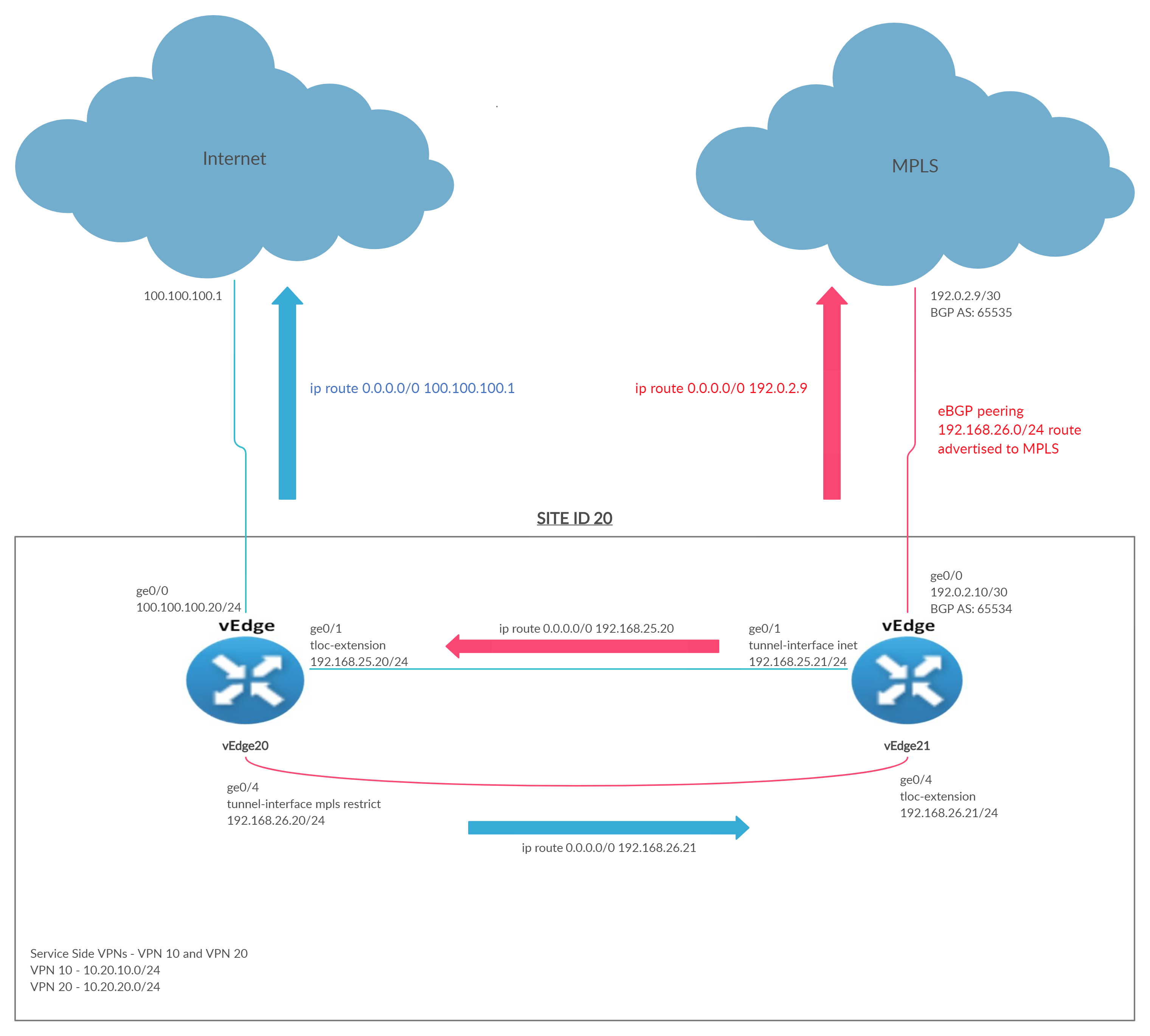
vEdge20 is connected to the Internet transport whereas vEdge21 is connected to MPLS. If the Internet link goes down, vEdge20 doesn’t have a way to utilize the MPLS link available at vEdge21. TLOC Extensions seek to remedy this.
vEdge/cEdge routers build IPSec tunnels across directly connected transports AND across the transport connected to the neighbouring vEdge/cEdge router to facilitate transport redundancy.
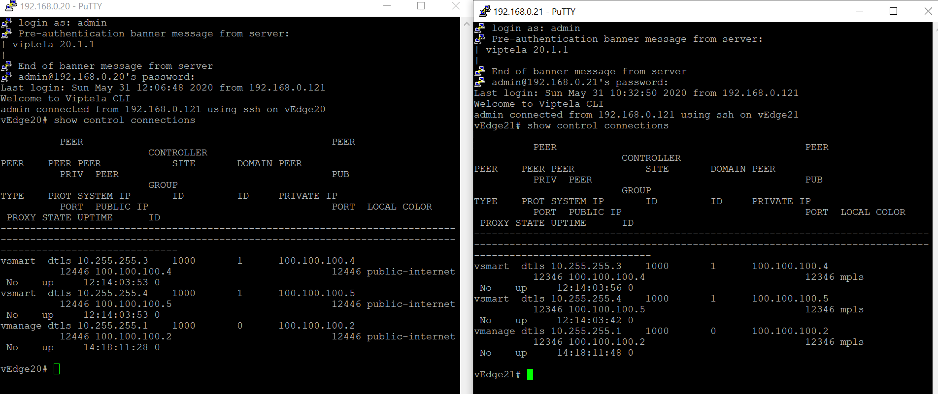
Without TLOC Extensions, the vEdges at Site 20 look something like the images below. Note that both have control connections to the vSmarts and vManage via the directly connected transport, which can be checked using the CLI show control connections
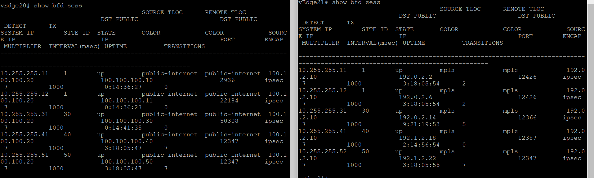
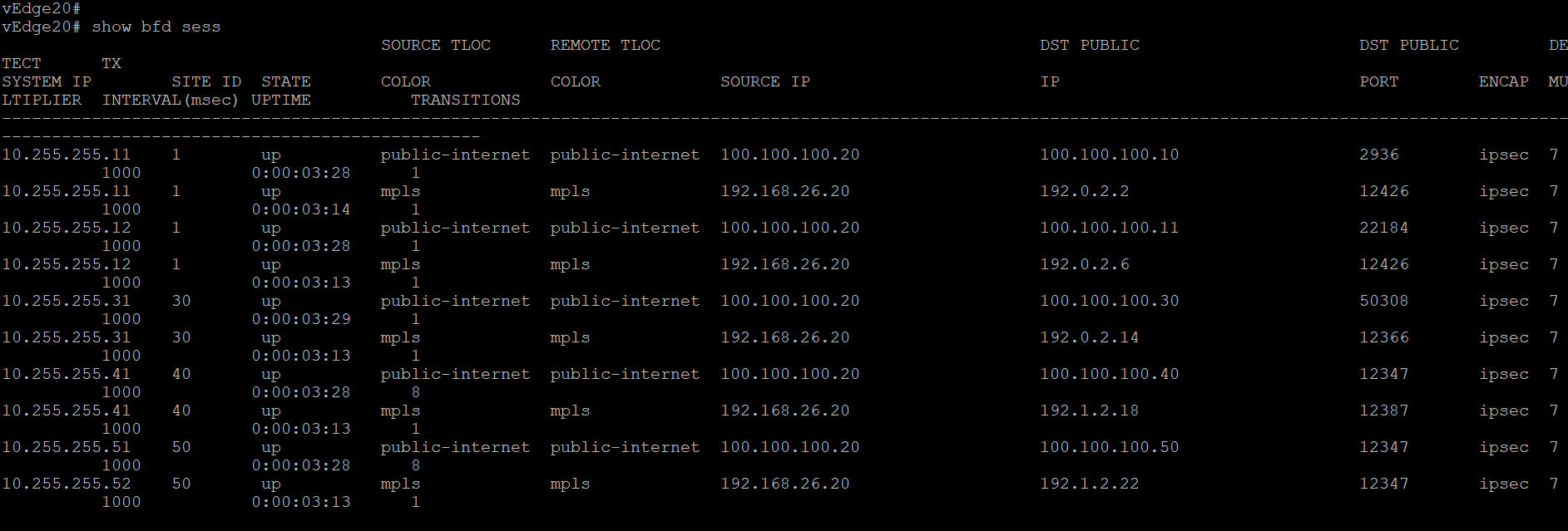
BFD sessions are established across the directly connected transport as well. Check via the CLI show bfd sessions
show control connections
show bfd sessions
-
- Feature Templates for TLOC Extensions
- Creating the VPN Interface Template for the TLOC-EXT interface
- Creating the VPN Interface Template for the Tunnel interface
- Creating the BGP Template for the MPLS link
- Updating the VPN and Device Templates
- Activity Verification
Feature Templates for TLOC Extensions
We will need to create a total of three Feature Templates for this section which will be applied to vEdge20 and vEdge21 Device Templates.
Towards the end of the lab, we will copy and modify the VPN 0 feature template used by the INET interface on vEdge20 to allow for NAT. Both vEdges at Site20 use the same feature template for VPN 0 ge0/0 so making a change on one will impact the other as well. Hence, we will be breaking off the vEdge20 VPN Interface template from the one being used. This new template will be identical to the VPN 0 interface template being used at this Site, except for NAT being enabled on ge0/0.
Creating the VPN Interface Template for the TLOC-EXT interface
-
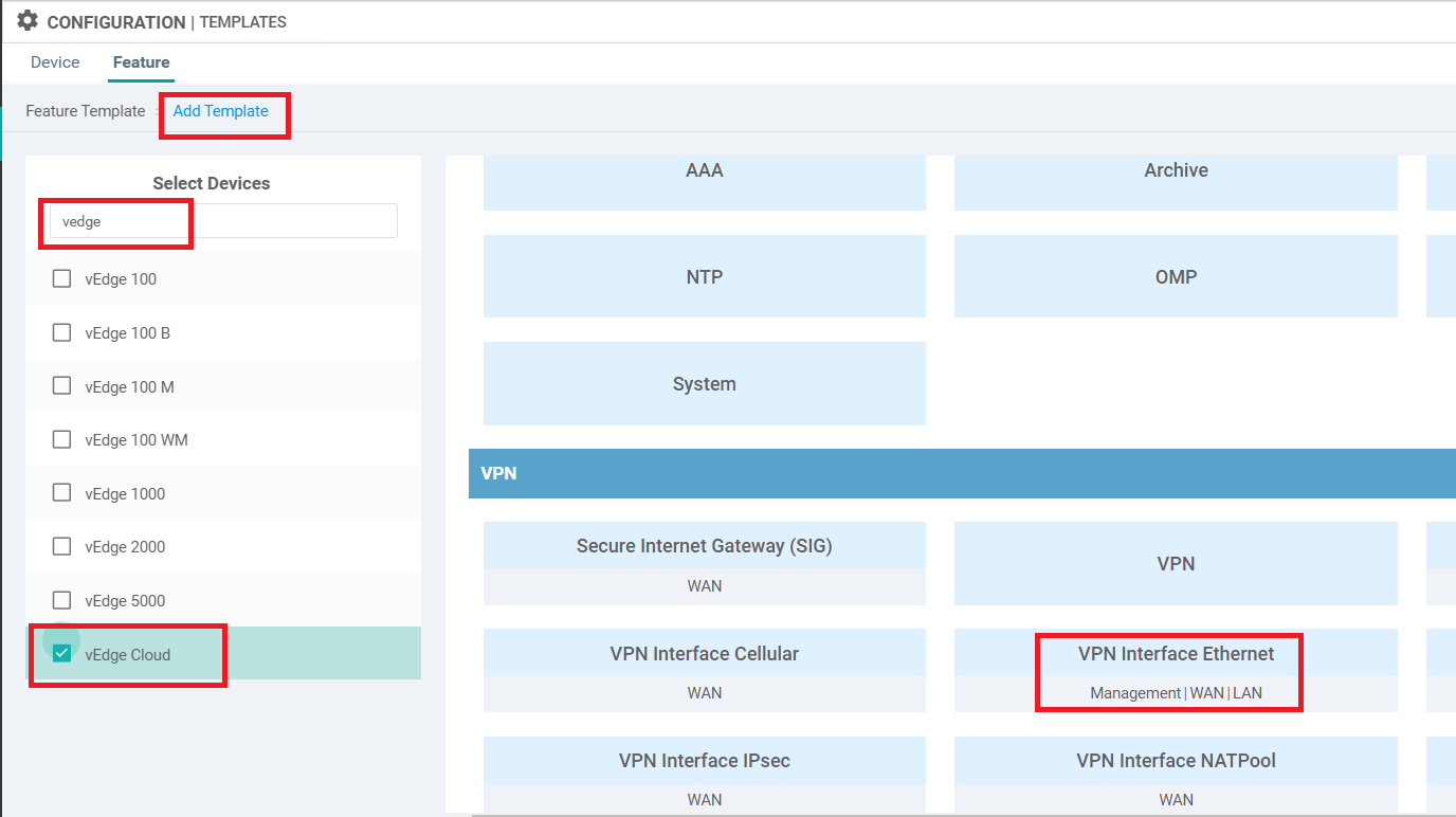
On the vManage GUI, click on Configuration => Templates and go to the Feature tab. click on Add Template and search for vedge. Select vEdge Cloud from the list and choose VPN Interface Ethernet to create an Interface Template
-
Enter the details as shown in the table below. Use the images for reference. Click on Save once done
Section Field Global or Device Specific (drop down) Value Template Name NA Site20_TLOC_Ext_NoTunn Description NA Site 20 TLOC Extension Template without Tunnel Configuration Basic Configuration Shutdown Global No Basic Configuration Interface Name Device Specific if_name_notunn_tlocext Basic Configuration IPv4 Address Device Specific if_ipv4_address_notunn Advanced TLOC Extension Global ge0/0 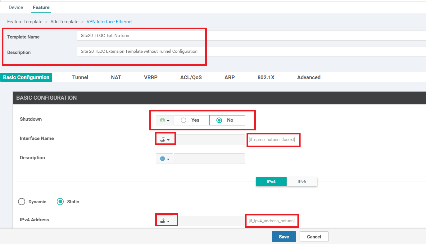
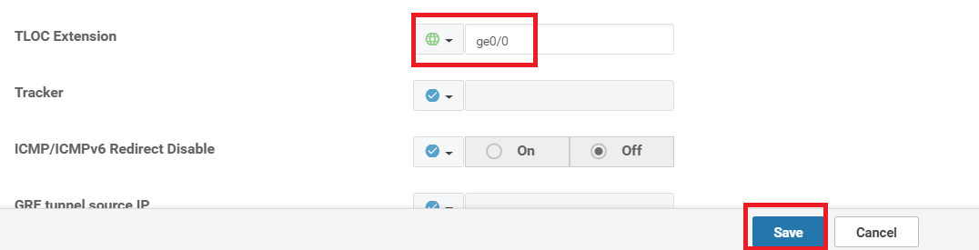
This completes configuration of the VPN Interface Template for TLOC Extension interfaces, without a Tunnel. Each participating vEdge/cEdge will have an interface that will not have a Tunnel associated with it (but will have a TLOC Extension association) and another one which will have a Tunnel (but won’t have a TLOC Extension associated with it).
-
- Feature Templates for TLOC Extensions
-
- Creating the VPN Interface Template for the Tunnel interface
- Creating the BGP Template for the MPLS link
- Updating the VPN and Device Templates
- Activity Verification
Creating the VPN Interface Template for the Tunnel interface
-
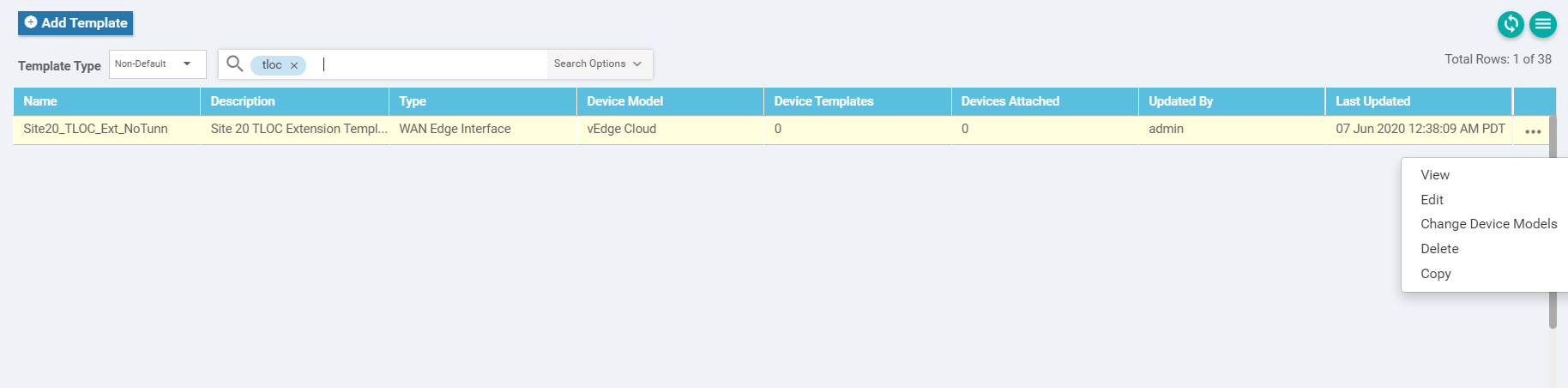
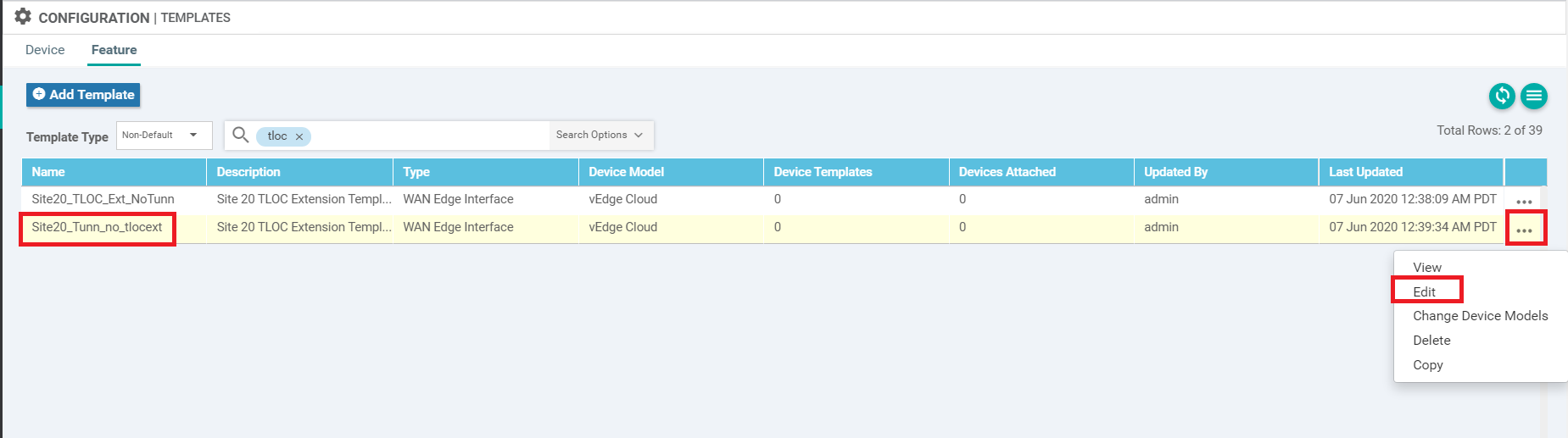
Navigate to Configuration => Templates => Feature tab and search for tloc. You should get one template (the one we just created). Click on the three dots next to it and choose Copy
-
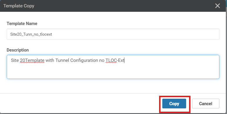
Rename the Template to Site20_Tunn_no_tlocext with a Description of Site 20 Template with Tunnel Configuration no TLOC-Ext. Click on Copy
-
Click on the three dots next to the newly created template and choose to Edit
-
Update the details as in the table below. Use the images for reference and click on Update when done
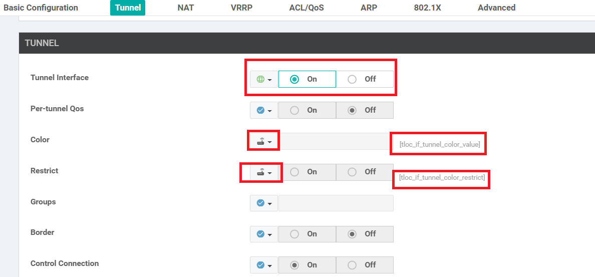
Section Field Global or Device Specific (drop down) Value Basic Configuration Shutdown Global No Basic Configuration Interface Name Device Specific if_name_tunn_notlocext Basic Configuration IPv4 Address Device Specific if_ipv4_address_tunn Tunnel Tunnel Interface Global On Tunnel Color Device Specific tloc_if_tunnel_color_value Tunnel Restrict Device Specific tloc_if_tunnel_color_restrict Tunnel - Allow Service All Global On Advanced TLOC Extension Default 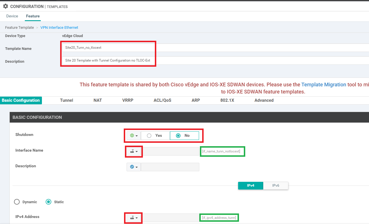
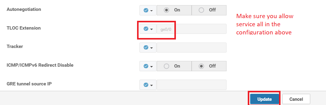
This completes the configuration of our second feature template.
-
- Feature Templates for TLOC Extensions
-
-
- Creating the BGP Template for the MPLS link
- Updating the VPN and Device Templates
- Activity Verification
Creating the BGP Template for the MPLS link
We will now set up the BGP template for eBGP peering on the MPLS link. This is so that the TLOC extension subnet (192.168.26.0/24 in this case) can be advertised to the MPLS network.
-
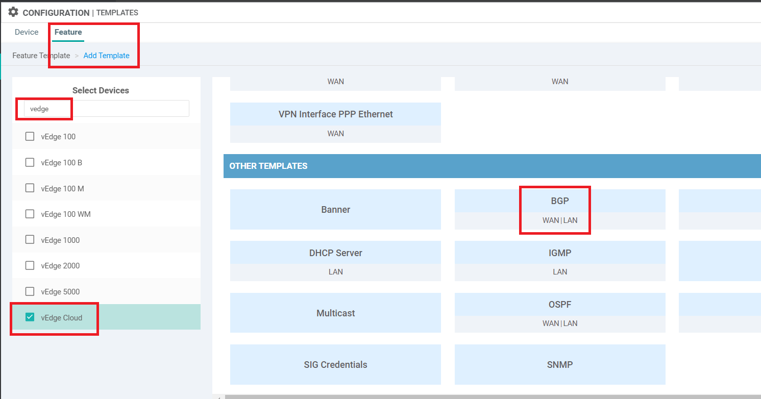
On the vManage GUI, go to Configuration => Templates => Feature tab. Click on Add Template and search for vedge. Select vEdge Cloud and scroll down to the Other Templates section. Choose BGP
-
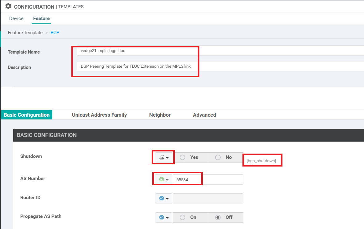
Enter the Template Name as vedge21_mpls_bgp_tloc and the Description as BGP Peering Template for TLOC Extension on the MPLS link. Set Shutdown to a Device Specific variable of bgp_shutdown. Set AS Number to a global value of 65534. This will be the AS number on our vEdge21 for BGP Peering
-
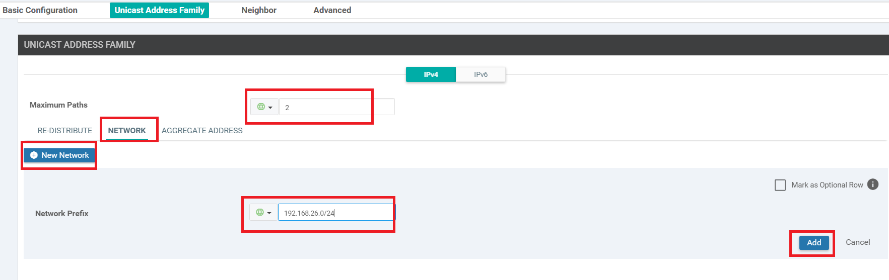
Under Unicast Address Family, set the Maximum Paths to 2. Click on the Network tab and click on New Network. Enter the Network Prefix as a global value of 192.168.26.0/24 and click on Add. This is the subnet which will be advertised in BGP
-
Under Neighbor, click on New Neighbor and enter details as per the table below. Click on Add (don’t miss this - far right corner) to Add the Neighbor details and then click on Save (bottom-middle of the screen) to Save this template
Section Field Global or Device Specific (drop down) Value Neighbor Address Global 192.0.2.9 Neighbor Remote AS Global 65535 Neighbor Address Family Global On Neighbor Address Family Global ipv4-unicast Tip: We are setting many of the fields to Global values since this is a lab environment. In production, it is recommended to set certain fields as Device Specific variables so that the templates can be re-used as and when required, for disparate device configurations. The best case scenario is to have as much common configuration between devices/sites as is possible (global values) and then create Device Specific variables for the uncommon parameters.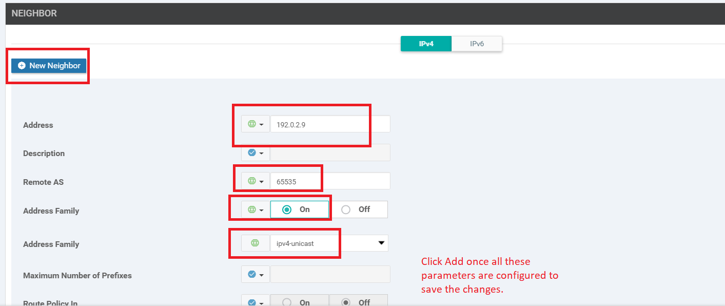
This completes the configuration of our BGP Template.
-
-
-
-
-
- Updating the VPN and Device Templates
- Activity Verification
Updating the VPN and Device Templates
We will start by updating the existing VPN template for Site 20 (named Site20-vpn0) to include a default route with a next hop to the corresponding TLOC Extension interface (i.e. to 192.168.26.21 on vEdge20 and 192.168.25.20 on vEdge21). Device Specific variables will be used.
-
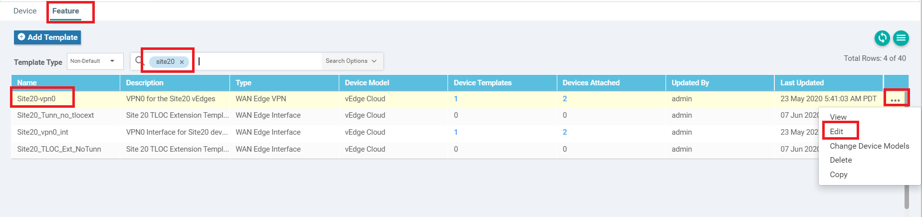
Navigate to Configuration => Templates => Feature tab on the vManage GUI. Search for site20 and you should see the Site20-vpn0 template. Click on the three dots next to it and choose to Edit
-
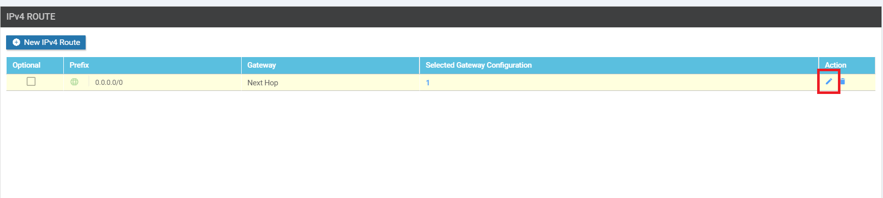
Scroll down to the IPv4 Route section and click on the pencil icon next to 0.0.0.0/0 route to edit it
-
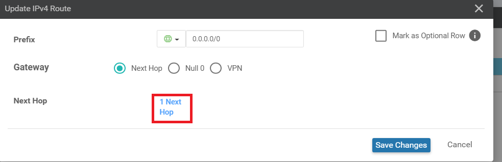
Click on 1 Next Hop in the Update IPv4 Route popup
-
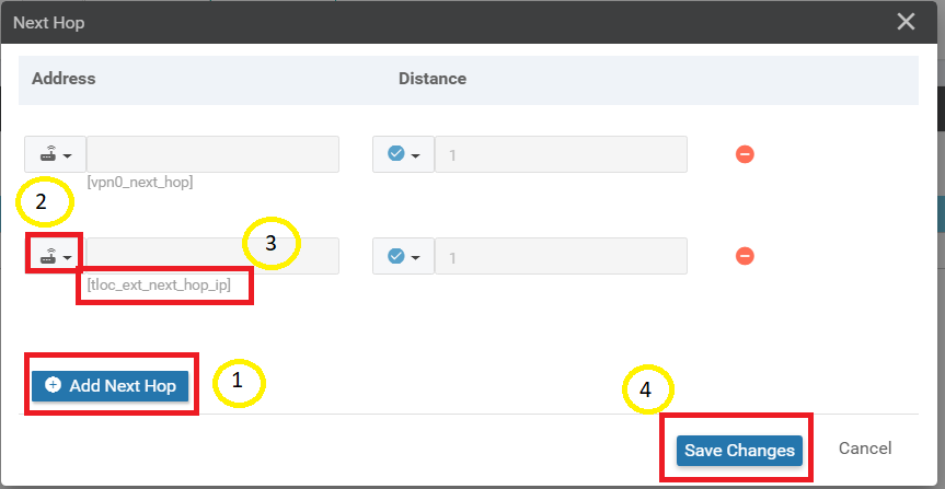
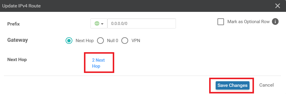
Click on Add Next Hop and set the new hop address to Device Specific with a name of tloc_ext_next_hop_ip. Click on Save Changes
-
Click on Save Changes again, making sure that the Update IPv4 Routes field now shows 2 Next Hop
-
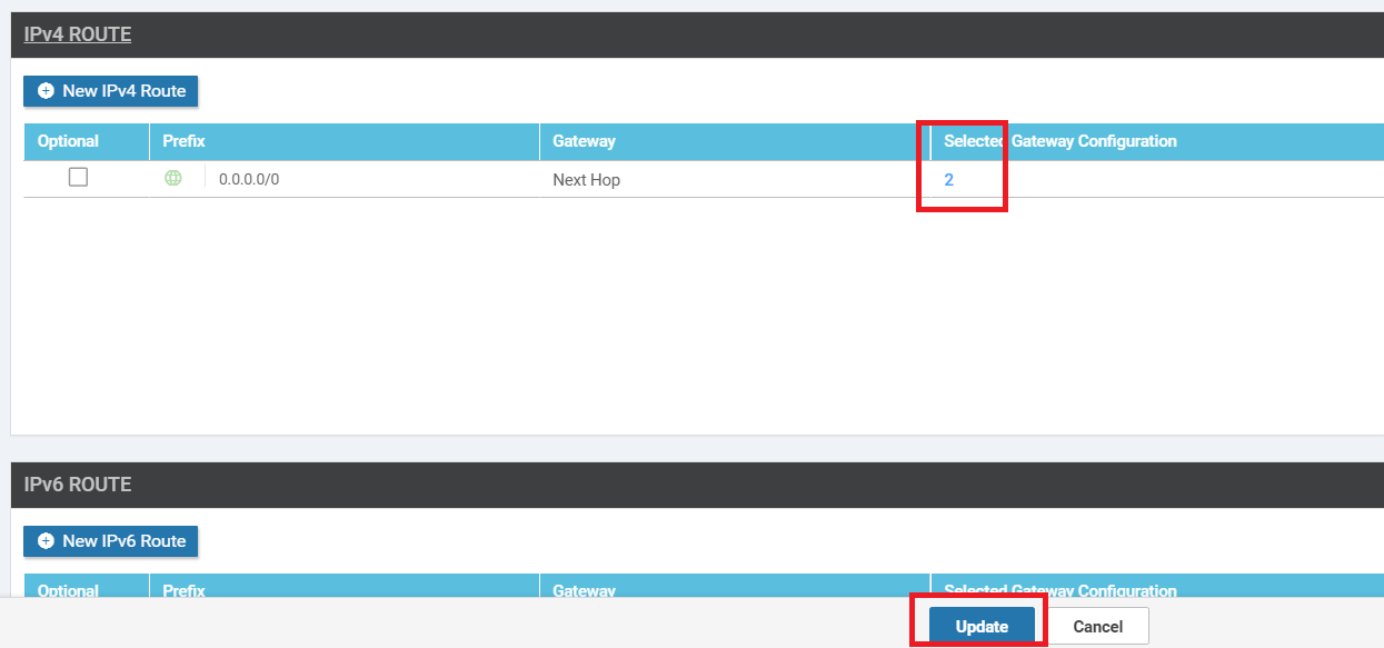
Back at the VPN Feature template, make sure that the number 2 shows up under Selected Gateway Configuration and click on Update
-
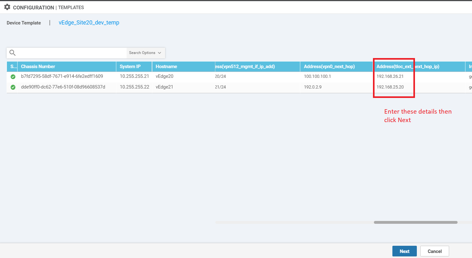
Populate the details for the Address (tloc_ext_next_hop_ip) for the two vEdges. vEdge20 should have 192.168.26.21 and vEdge21 should have 192.168.25.20 as the next hop IP. Click on Next
-
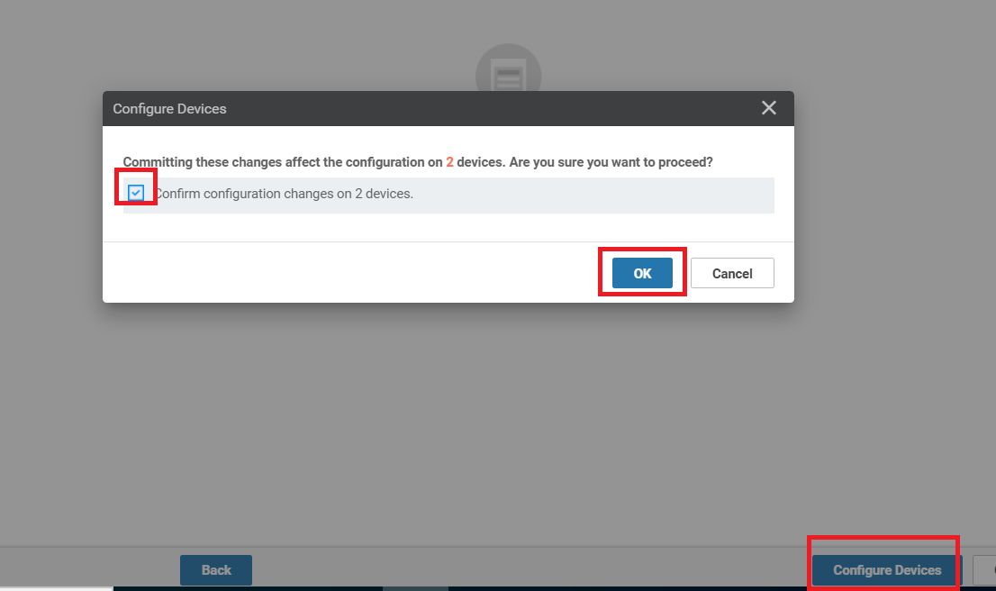
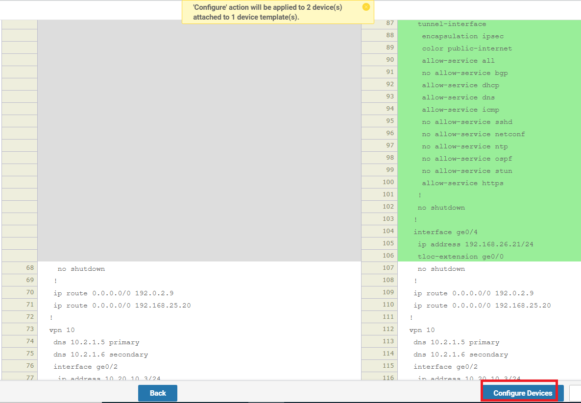
You can view the side by side configuration if needed, and click on Configure Devices. Choose the confirm the changes and click on OK
-
To edit the Device Template and bring everything together, navigate to Configuration => Templates on the vManage GUI. Make sure you’re on the Device tab and locate the vedge_Site20_dev_temp template. Click on the three dots next to it and choose to Edit
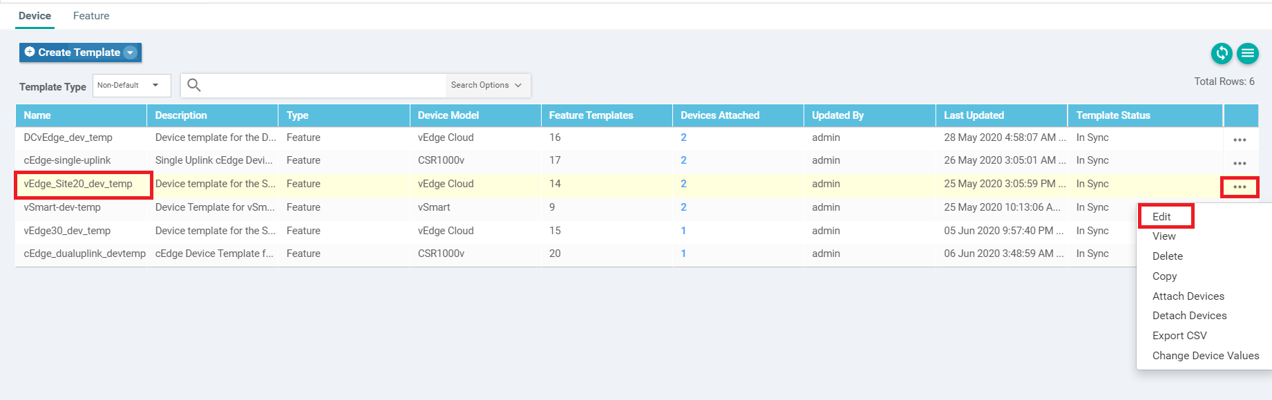
-
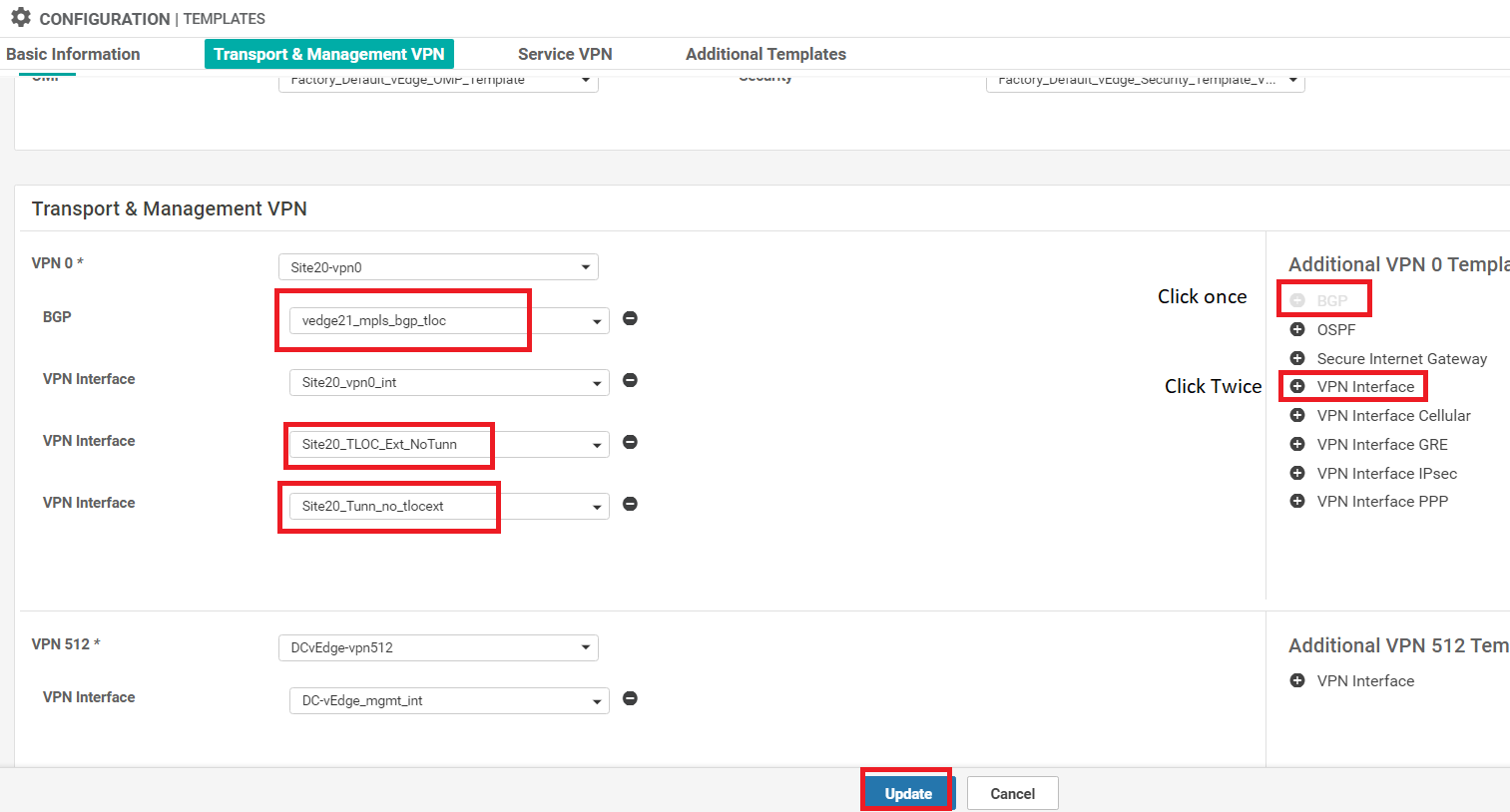
Under Transport & Management VPN, click on BGP under Additional VPN 0 Templates. Click on VPN Interface twice to add two VPN Interfaces over on the left-hand side. Populate the BGP template we created in the BGP field (named vedge21_mpls_bgp_tloc). Populate Site20_TLOC_Ext_NoTunn under the first VPN Interface and Site20_Tunn_no_tlocext under the second VPN Interface. Click on Update
-
Click on the three dots next to vEdge20 and choose Edit Device Template. Enter the details as shown in the table below, referencing the image and click on Update
Field Value Interface Name (if_name_tunn_notlocext) ge0/4 IPv4 Address (if_ipv4_address_tunn) 192.168.26.20/24 Color (tloc_if_tunnel_color_value) mpls Restrict (tloc_if_tunnel_color_restrict) Checked Interface Name (if_name_notunn_tlocext) ge0/1 IPv4 Address (if_ipv4_address_notunn) 192.168.25.20/24 Shutdown (bgp_shutdown) Checked 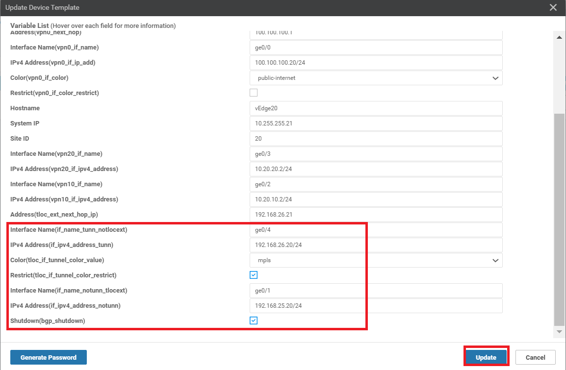
-
Click on the three dots next to vEdge21 and choose Edit Device Template. Enter the details as shown in the table below, referencing the image and click on Update and then click on Next
Field Value Interface Name (if_name_tunn_notlocext) ge0/1 IPv4 Address (if_ipv4_address_tunn) 192.168.25.21/24 Color (tloc_if_tunnel_color_value) public-internet Restrict (tloc_if_tunnel_color_restrict) Unchecked Interface Name (if_name_notunn_tlocext) ge0/4 IPv4 Address (if_ipv4_address_notunn) 192.168.26.21/24 Shutdown (bgp_shutdown) Unchecked 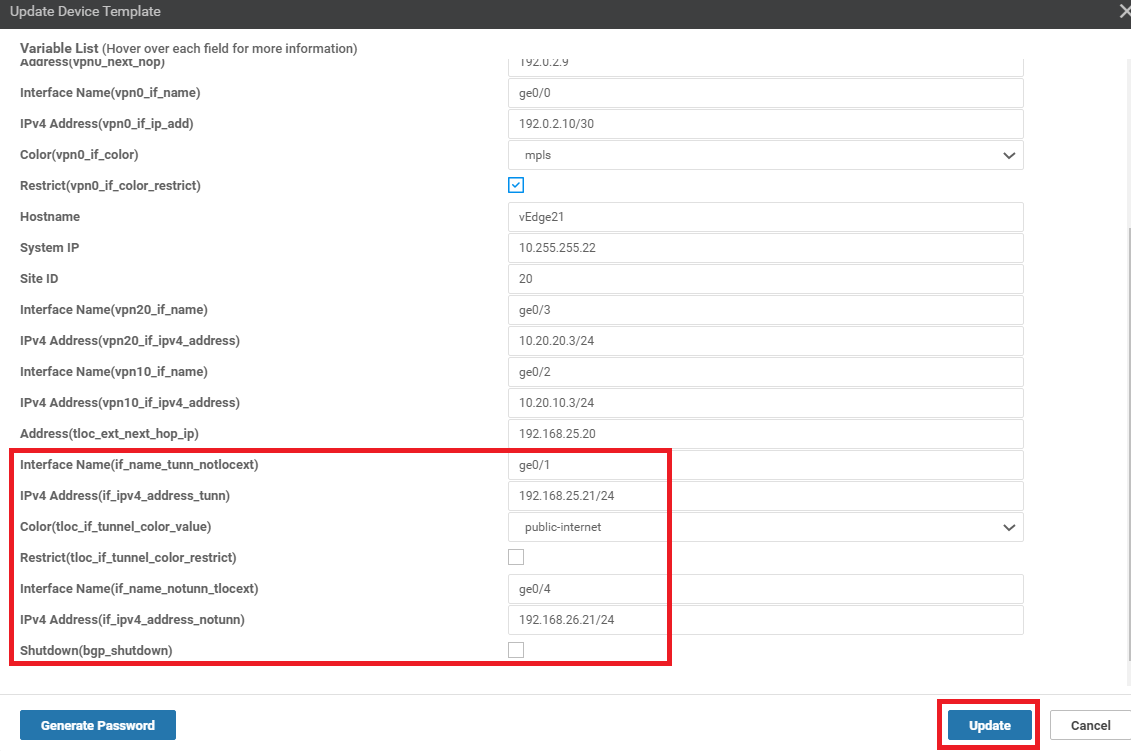
-
View the side-by-side configuration (optional) and click on Configure Devices. Confirm the configuration change on 2 devices
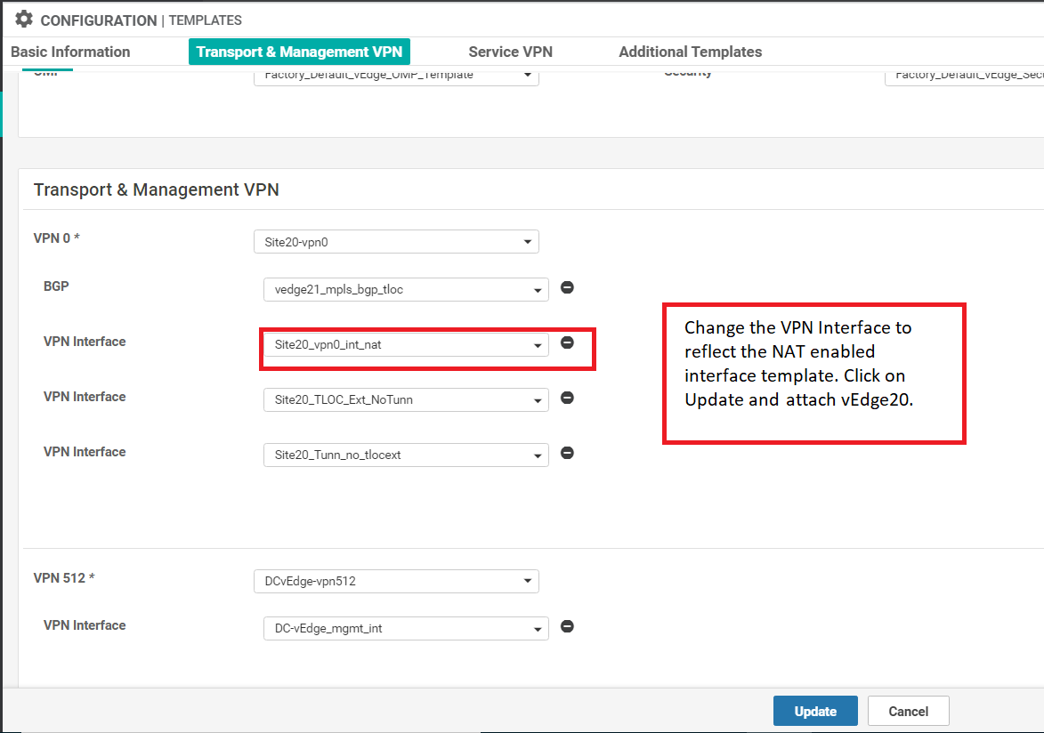
 Tip: It’s important to make another change to the Internet transport so that our TLOC Extension configuration works as expected. We need to enable NAT on the VPN Interface associated with the Internet link. Unfortunately, NAT can’t be enabled/disabled via Device Specific parameters so we will need to copy the VPN Interface template, tweak it and then copy the Device Template to reference the new VPN Interface template. We will then attach vEdge20 to this template.
 -
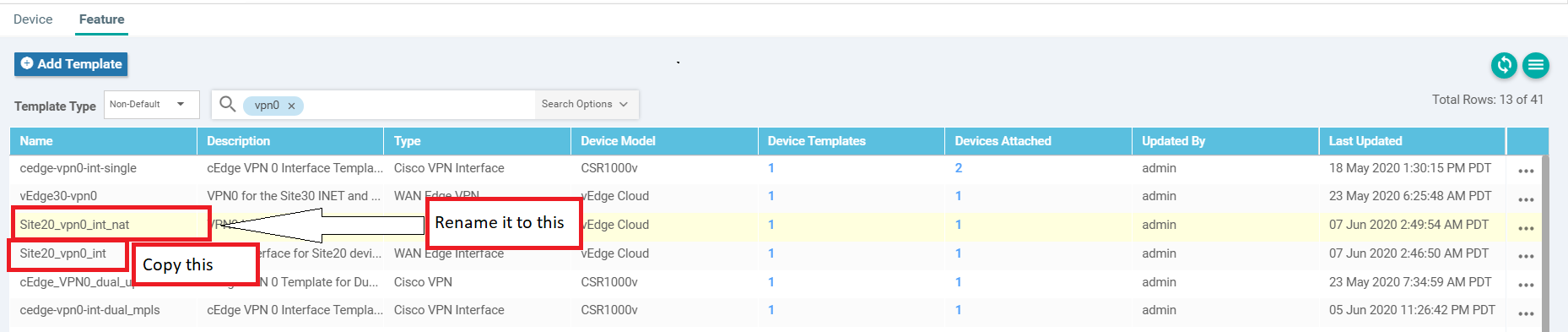
From the vManage GUI, navigate to Configuration => Templates. On the Feature tab, search for vpn0. Locate the site20_vpn0_int template and make a copy of it, renaming to site20_vpn0_int_nat and updating the description accordingly
-
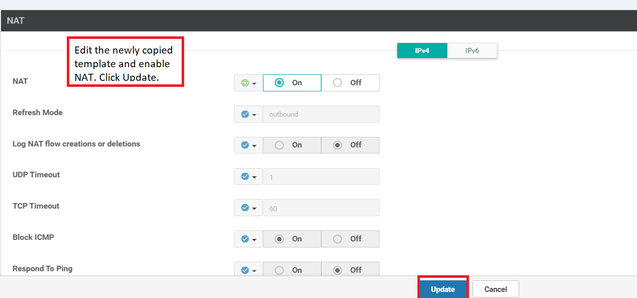
Click on the three dots next to the new site20_vpn0_int_nat template and choose to Edit. Set NAT to a global value of On and click on Update
-
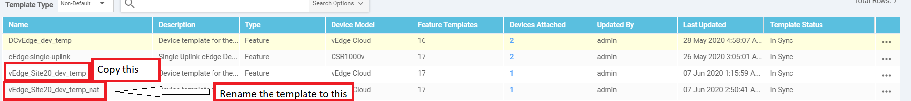
Make sure you’re on the Configuration => Templates Device tab and locate the vEdge_Site20_dev_temp template. Make a copy of it, renaming to vEdge_Site20_dev_temp_nat and updating the description accordingly
-
Choose to Edit the newly created vEdge_Site20_dev_temp_nat via the three dots next to it and update the VPN Interface field under Transport & Management VPN to reflect the VPN Interface template we created in step 14/15. The name of the newly created VPN Interface template is site20_vpn0_int_nat. Click on Update
-
Click on the three dots next to the vEdge_Site20_dev_temp_nat device template and click on Attach. Choose the vEdge20 device and Attach it. Click Next/Configure Device as the prompts pop up (nothing will need to be populated since we’re using a device template copied from before with NAT set to On)
Important: Wait for the template to attach. If it gives an error/failure then the templates will go out of sync. To resync, click on the three dots next to vEdge_Site20_dev_temp and choose Change Device Values. Hit Next and Configure Devices. Now try step 18 above again.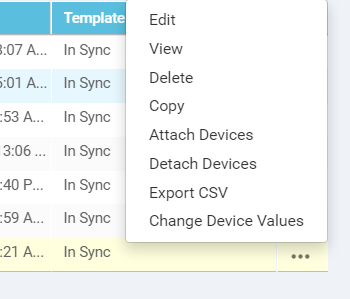
This completes the configuration of TLOC Extensions at Site 20.
-
-
-
-
-
-
- Activity Verification
Activity Verification
-
To verify that our configuration is working, log in to the CLI of vEdge20 and vEdge21. Issue the same commands as before and compare with the output we had taken at the start of this section ( click here to compare the output). Output of
show control connectionsandshow bfd sessionsgiven below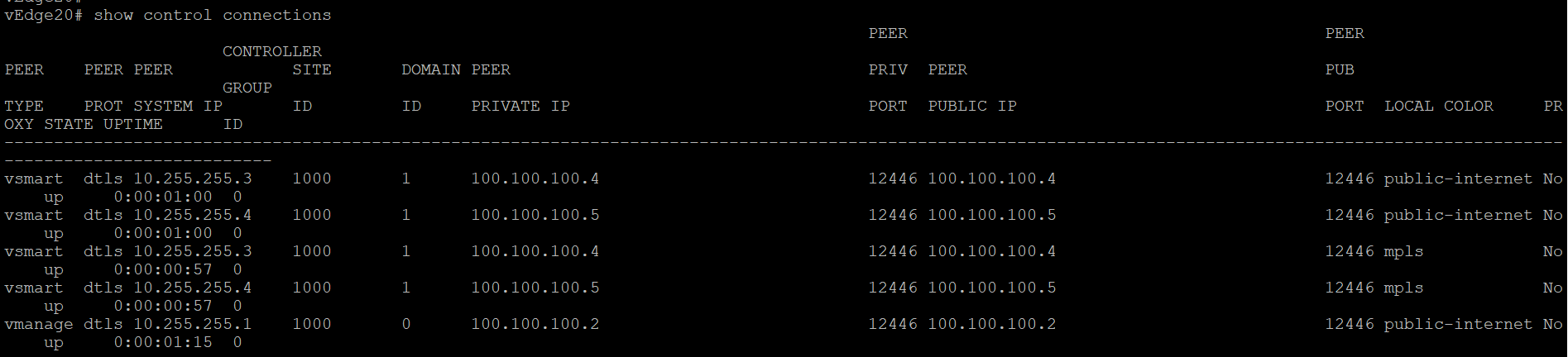
 Note: If you get output that looks like the image below for vEdge20 (i.e. there are 3 mpls TLOC control connections and 2 public-internet connections, issue a
clear control connections, wait for a couple of minutes and runshow control connectionsagain. The output should match with what we see above.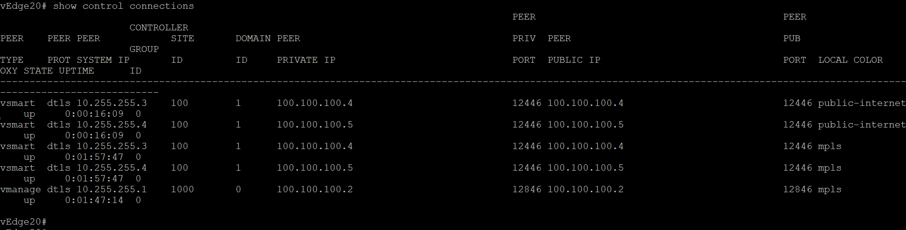
Issued
clear control connections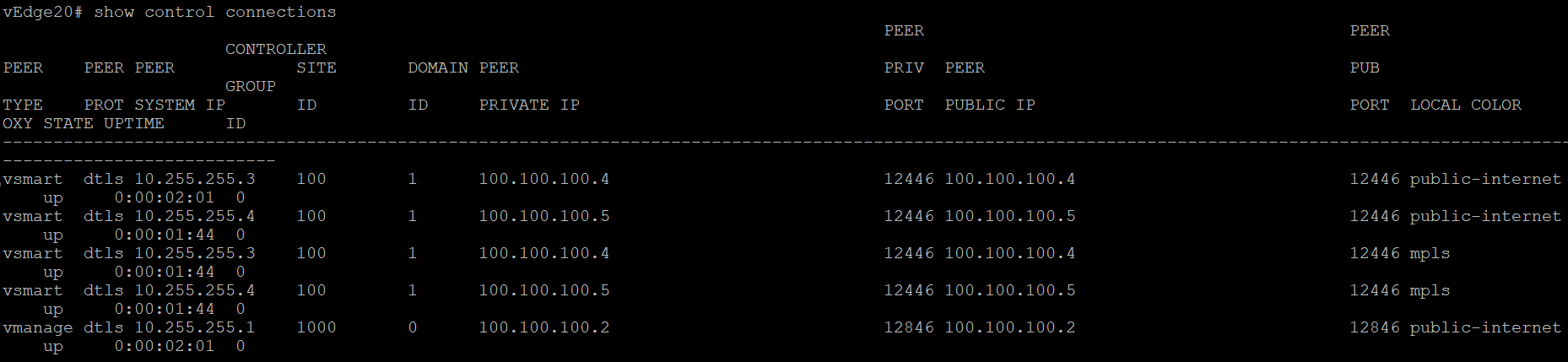
-
Similarly, log in to vEdge21 and compare the output of the same commands (click here to compare the output). Commands are again
show control connectionsandshow bfd sessions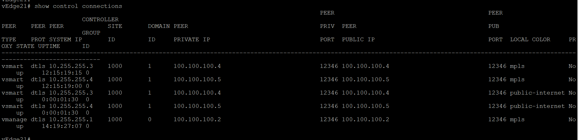
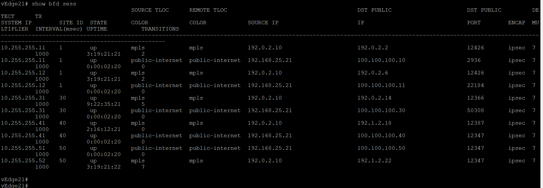
We now see that the vEdges have established control connections over the transport connected to their counterpart at the same site. BFD sessions are also established across the platform transports. Thus, we should see control connections and bfd sessions across mpls on vEdge20 and across public-internet on vEdge21, along with their directly connected transport connections/sessions.