- Overview
- Configure VPN 40 on DC-vEdges
- Configuration Cleanup and Routing Verification
- Setting up VPN Lists
- Inter VPN Routing Policies
- Inter VPN Routing Verification
- Policies for Service Chaining
- Activity Verification
Overview
As of now, devices in different VPNs cannot communicate with each other. VPN 10 devices can talk to other VPN 10 devices but not to VPN 20. In this section, we will be setting up Inter VPN routing.
Additionally, there might be a requirement where we need to send traffic from one VPN to another through a firewall. This feature is known as Service Chaining (other devices like Load Balancers can also be part of the Service Chain) and is used widely in real-world SD-WAN Deployments.
We will be focussing on ensuring devices in Site 20 VPN 10 can communicate with devices in Site 30 VPN 20. Initially, this will be direct communication between the two VPNs. A firewall will then be inserted in the path so that all traffic between the VPNs traverses the firewall, which will be located at Site-DC in VPN 40.
Diagrammatically, our topology will look as below:
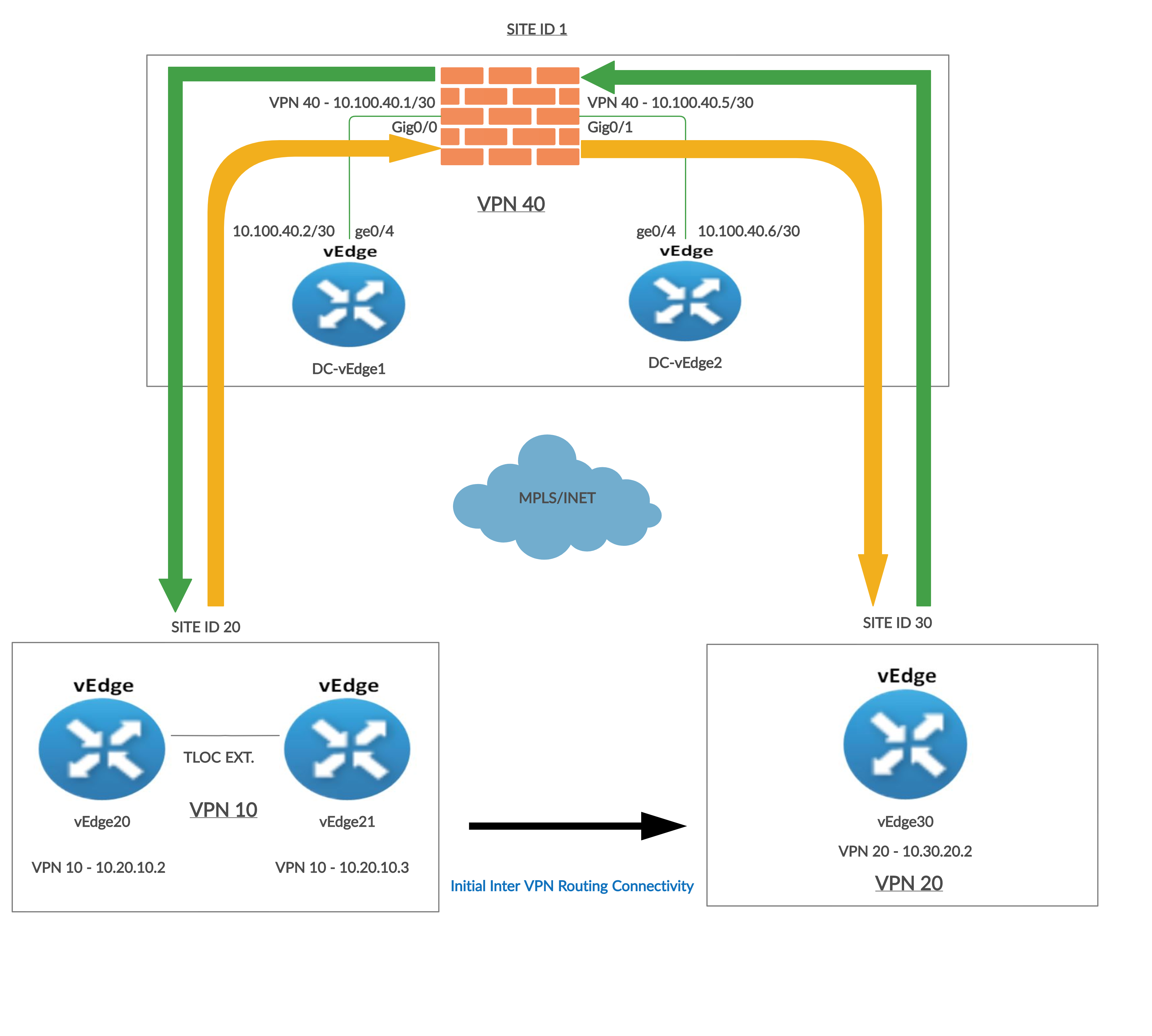
The Black arrow between Site 20 and Site 30 indicates the traffic flow when Inter VPN Routing configuration is done for the first time. Traffic flows directly between the two Sites.
The Orange arrow is the traffic flow from Site 20 VPN 10 to Site 30 VPN 20 once Service Chaining is configured.
Source IP: 10.20.10.2 or 10.20.10.3
Destination IP: 10.30.20.2
The Green arrow is the traffic flow from Site 30 VPN 20 to Site 20 VPN 10 once Service Chaining is configured.
Source IP: 10.30.20.2
Destination IP: 10.20.10.2 or 10.20.10.3
-
- Configure VPN 40 on DC-vEdges
- Configuration Cleanup and Routing Verification
- Setting up VPN Lists
- Inter VPN Routing Policies
- Inter VPN Routing Verification
- Policies for Service Chaining
- Activity Verification
Configure VPN 40 on DC-vEdges
We will configure VPN 40 at the DC Site and ensure connectivity between the DC-vEdges and the ASAv Firewall.
-
Log in to vCenter using the bookmark or by going to 10.2.1.50/ui if connected to the GHI DC and 10.1.1.50/ui if connected to the SJC DC from a web browser. Use the credentials for your POD
Username Password sdwanpodX
(X is your POD number)C1sco12345 
-
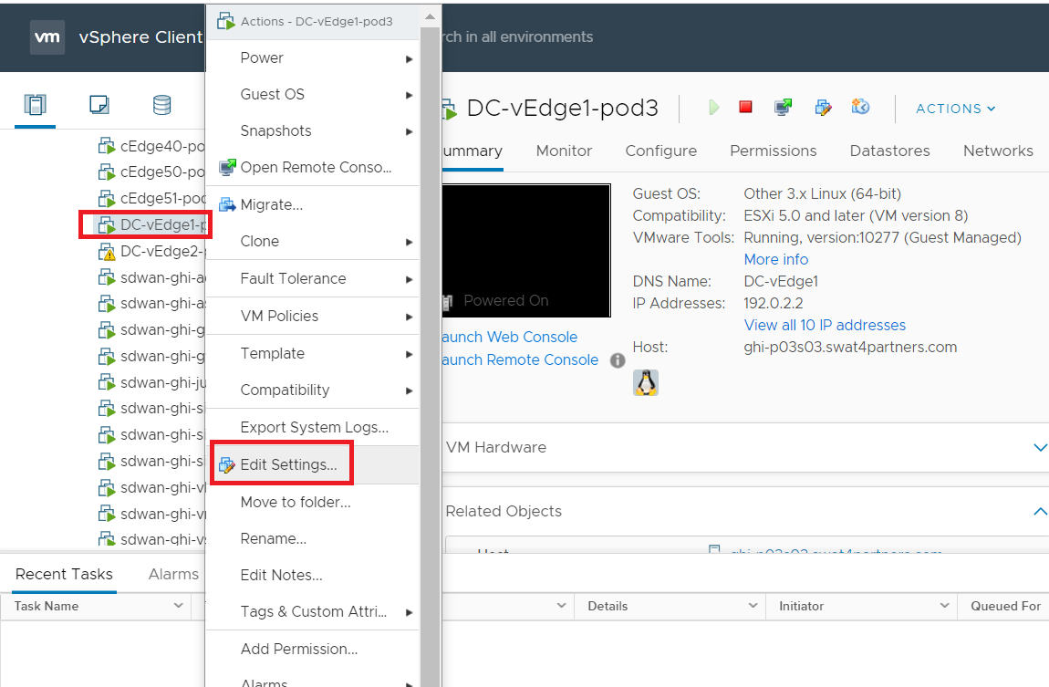
Right click on the DC-vEdge1-podX VM (where X is your POD number) and go to Edit Settings
-
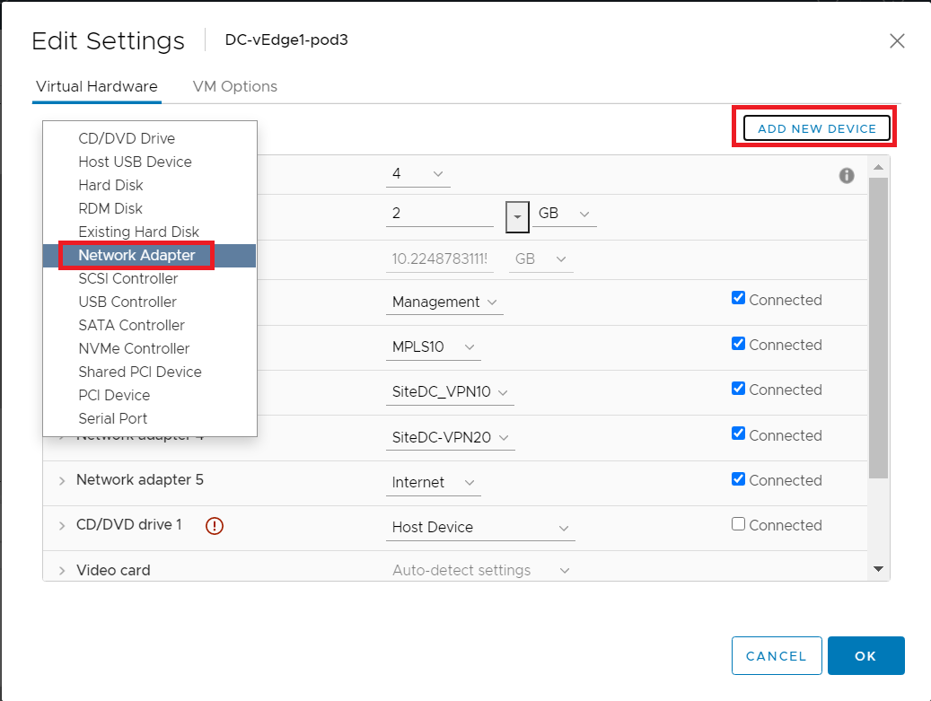
Click on Add New Device and choose to add a new Network Adapter. Repeat this process to add another Network Adapter
-
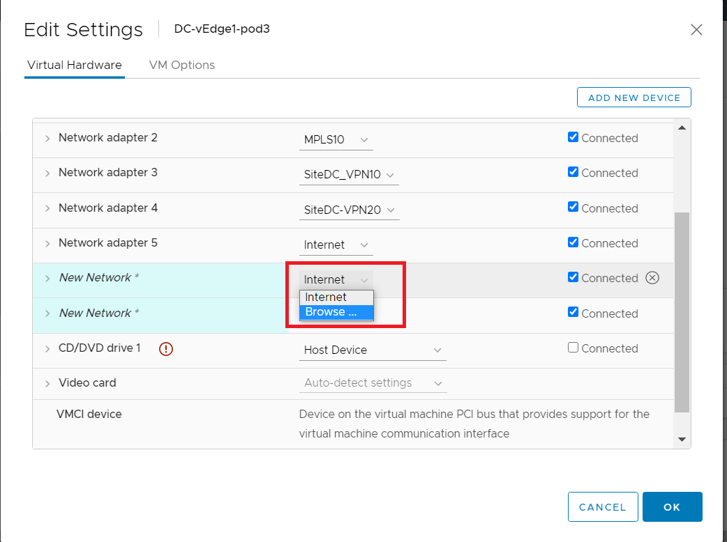
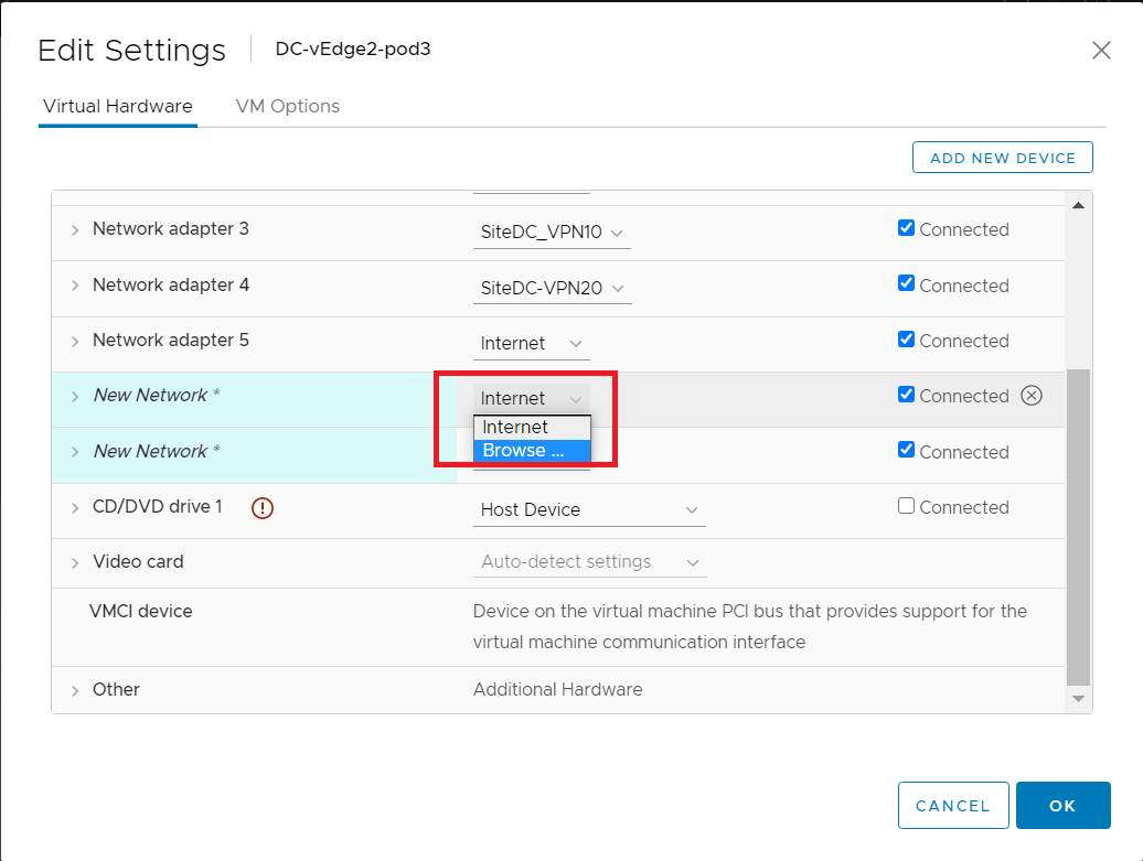
You should have two new network adapters. Click on the drop down next to the assigned network (Internet in the image below) for the first network adapter and click Browse
-
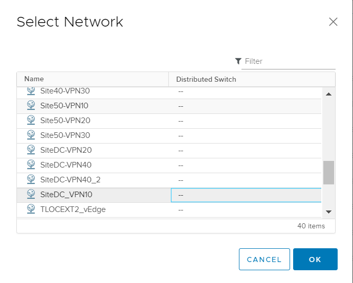
Choose SiteDC_VPN10 and click on OK
-
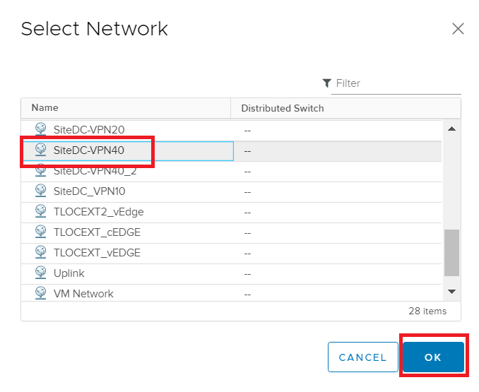
This takes you back to the Edit Settings page. Click on the drop down next to the assigned network for the second network adapter and click Browse. Select SiteDC-VPN40 and click on OK
-
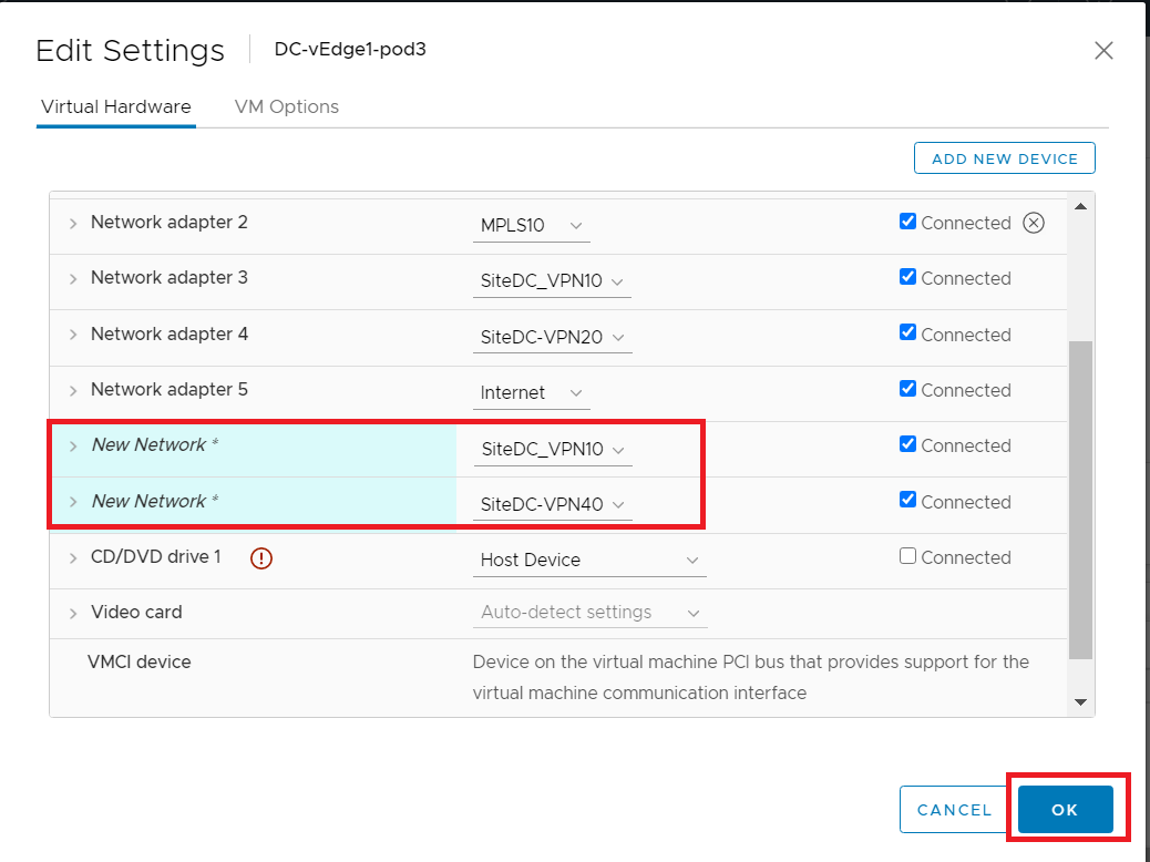
Make sure the settings match with the image given below and click on OK
-
Log in to DC-vEdge1 via Putty. You can use the saved session or SSH to 192.168.0.10 along with the credentials given below
Username Password admin admin 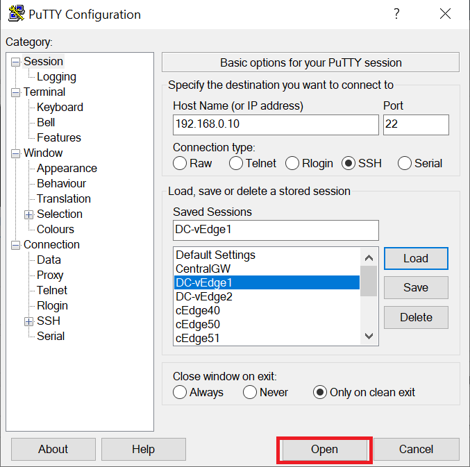
-
Type
rebootand thenyesto confirm the reboot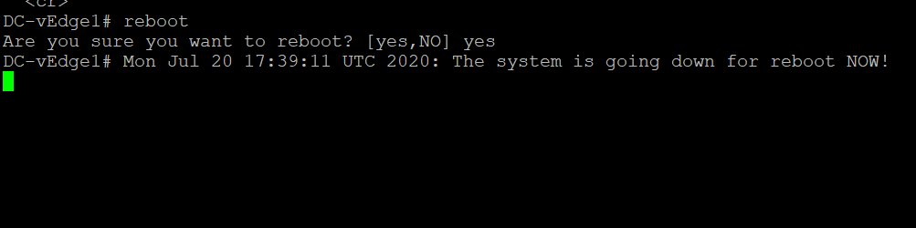
reboot yes -
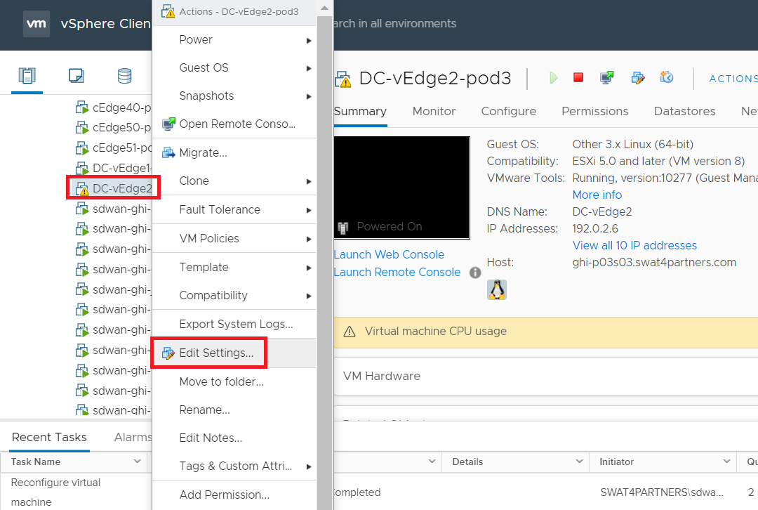
While the DC-vEdge1 vEdge is rebooting, head over to vCenter and right click on the DC-vEdge2-podX VM. Click on Edit Settings
-
Like before, add two network adapters by clicking on Add New Device and selecting Network Adapter. Make sure you add two network adapters. Click on the drop down for the first Network Adapter and choose Browse
-
Select SiteDC_VPN10 and click on OK
-
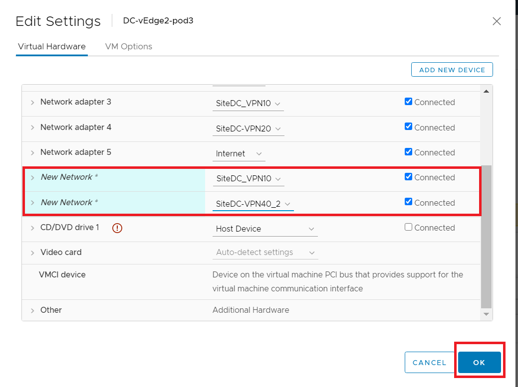
Click on the drop down next to the second network adapter and click on browse. Select SiteDC-VPN40_2 and click on OK. The network adapters should look like the image below
-
Log in to DC-vEdge2 via Putty, using the credentials below
Username Password admin admin 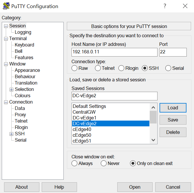
-
Type
show interface ?and notice that there are 4 “ge” interfaces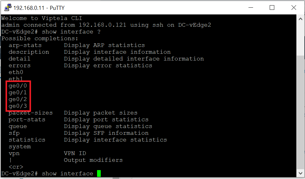
show interface ? -
Type
rebootand thenyesto confirm the reboot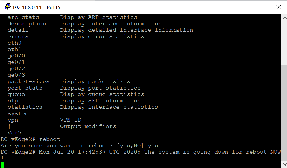
reboot yes -
Once DC-vEdge1 and DC-vEdge2 are back up, log in to either device and issue
show interface ?again. You will notice two additional interfaces - ge0/4 and ge0/5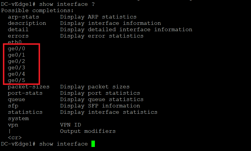
-
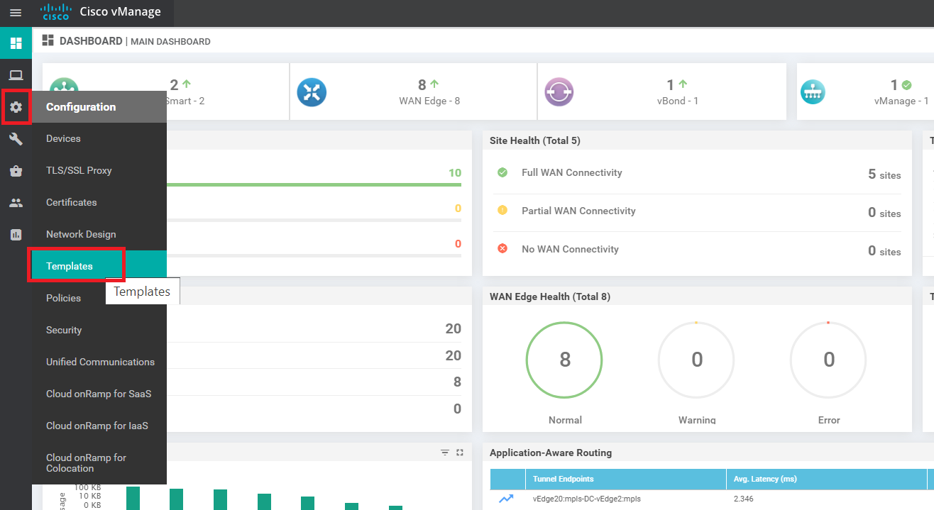
Log in to the vManage GUI using the bookmark or by going to 192.168.0.6 on a web browser. Click on Configuration => Templates
-
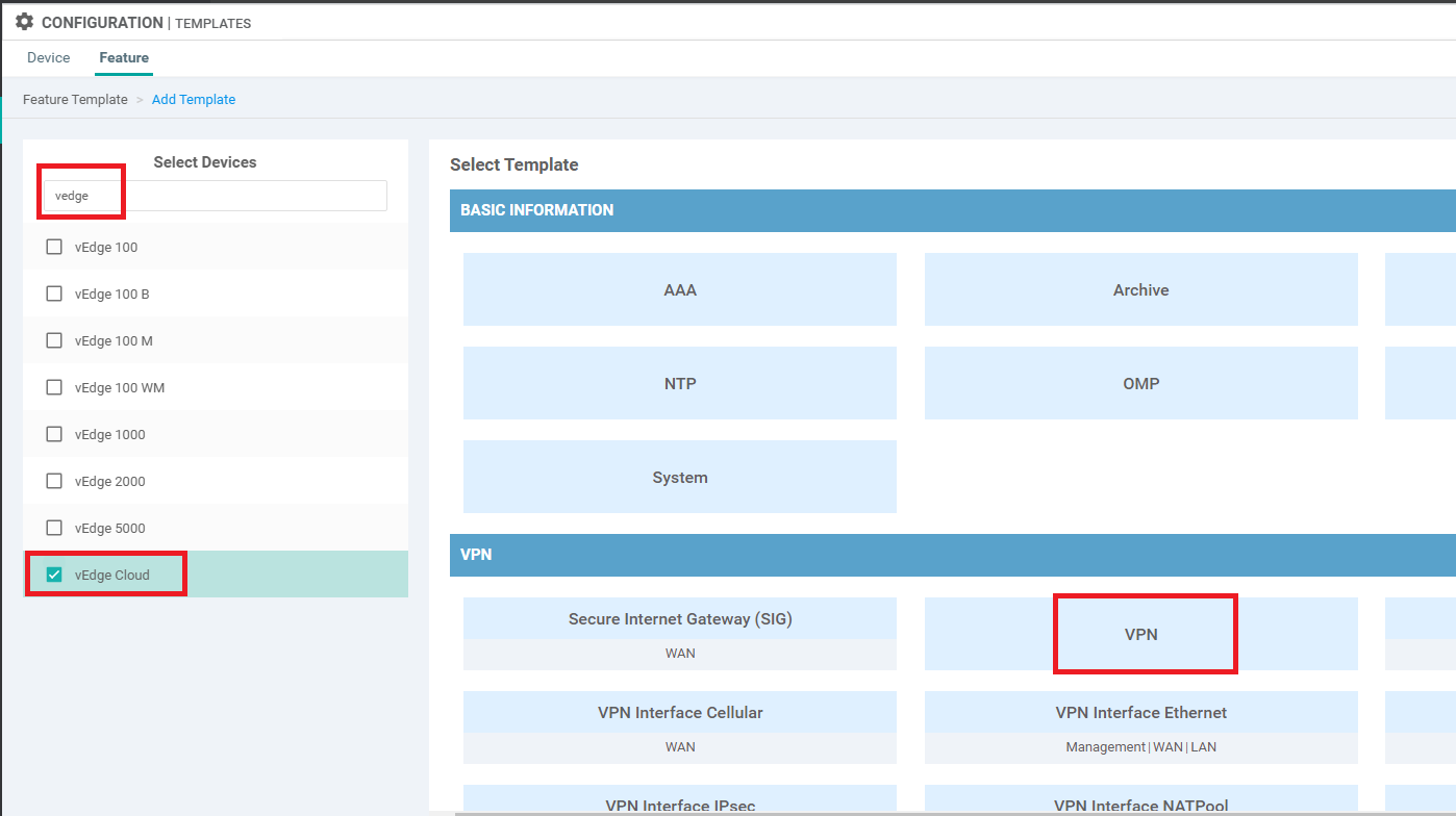
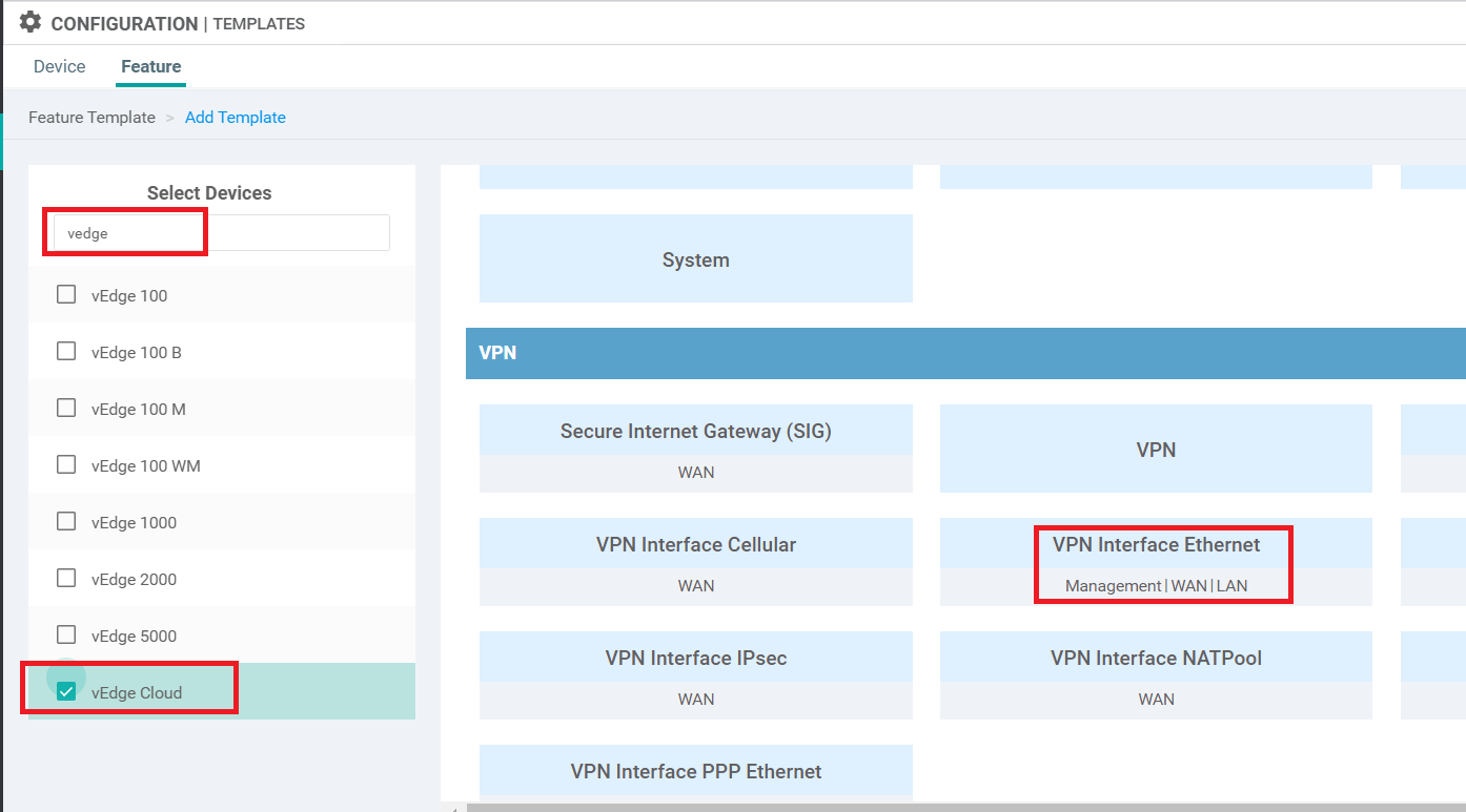
Go to the Feature tab and click on Add Template. Search for vedge and put a check mark next to vEdge Cloud. Choose VPN to create a VPN Template
-
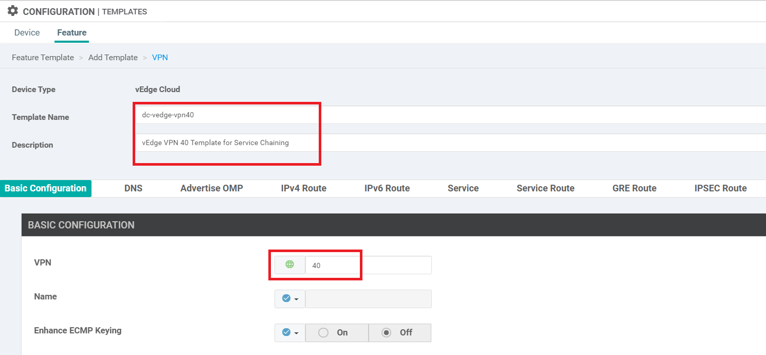
Give a Template Name of dc-vedge-vpn40 and a Description of vEdge VPN 40 Template for Service Chaining. Put the VPN as 40
-
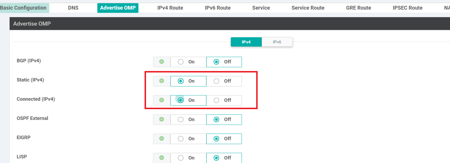
Scroll down to the Advertise OMP section and set Static (IPv4) and Connected (IPv4) to On
-
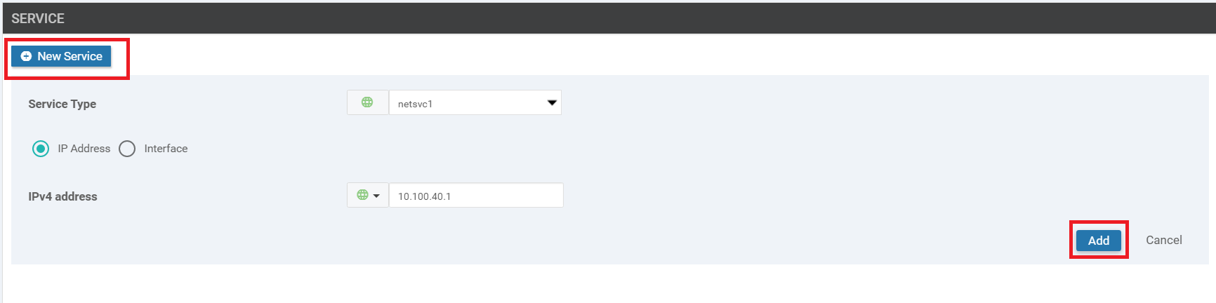
Go to the Service section and click on New Service. Select the Service Type as netsvc1 and enter an IPv4 Address of 10.100.40.1. Click on Add
-
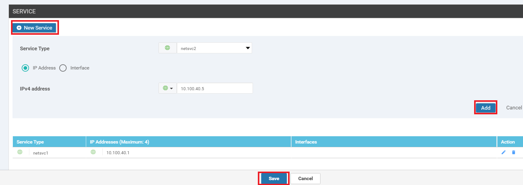
Click on New Service again and select the Service Type as netsvc2. Enter an IPv4 Address of 10.100.40.5. Click on Add then click on Save to save the VPN Template configuration
-
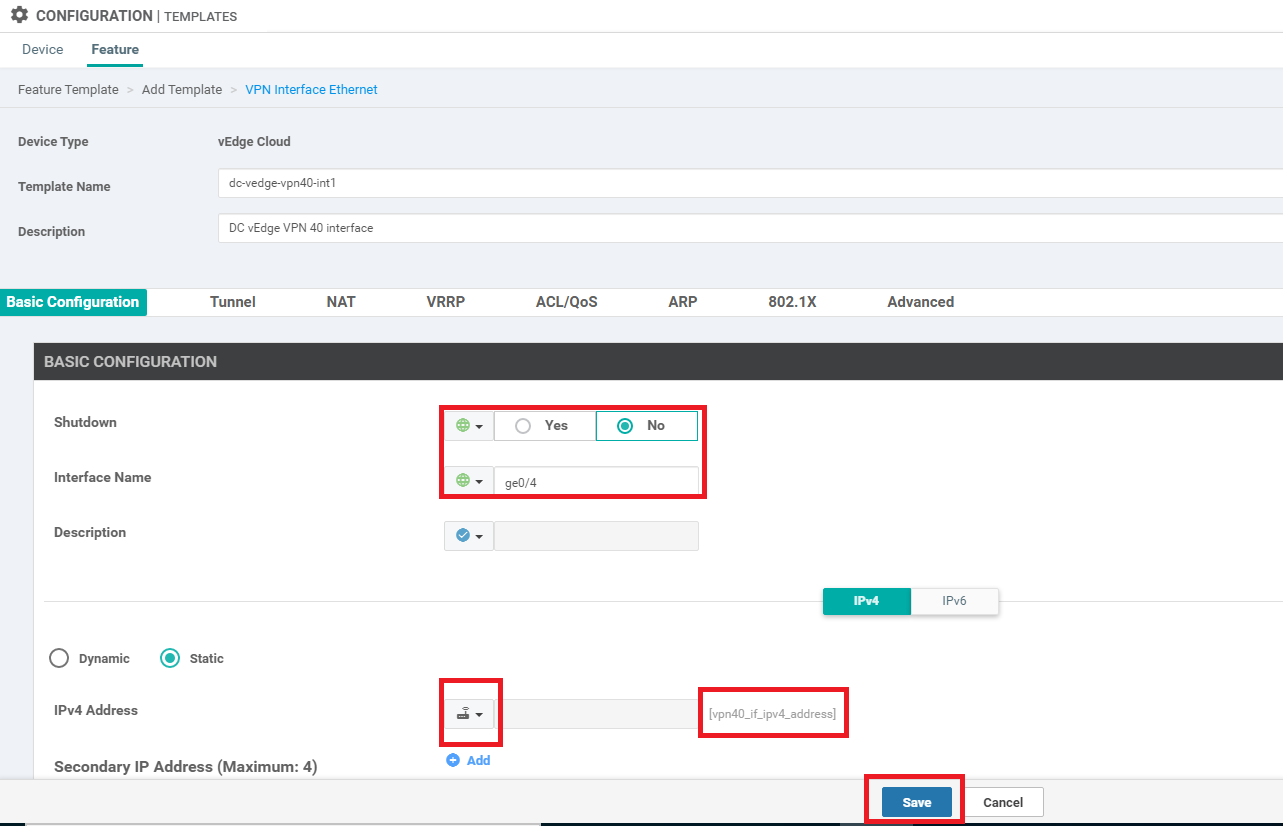
At the Configuration => Templates => Feature Tab page, click on Add Template. Search for vedge and select vEdge Cloud. Choose VPN Interface Ethernet as the Template Type
-
Give a Template Name of dc-vedge-vpn40-int1 with a Description of DC vEdge VPN 40 interface. Set Shutdown to No and the Interface Name as a Global value of ge0/4. Set the IPv4 Address to a Device Specific value of vpn40_if_ipv4_address and click on Save
-
Go to Configuration => Templates on the vManage GUI and make sure you’re on the Device tab. Locate the DCvEdge_dev_temp template and click on the three dots next to it. Choose to Edit the template
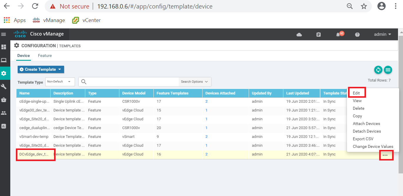
-
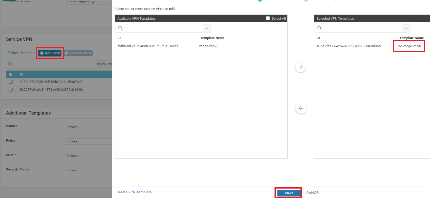
Scroll down to the Service VPN section and click on Add VPN. Move the dc-vedge-vpn40 template to the right-hand side and click on Next
-
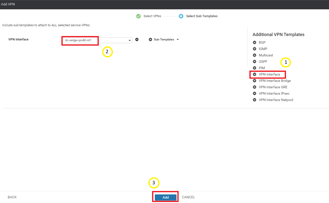
Click on VPN Interface under Additional VPN Templates and select dc-vedge-vpn40-int1 under the VPN Interface drop down. Click on Add
-
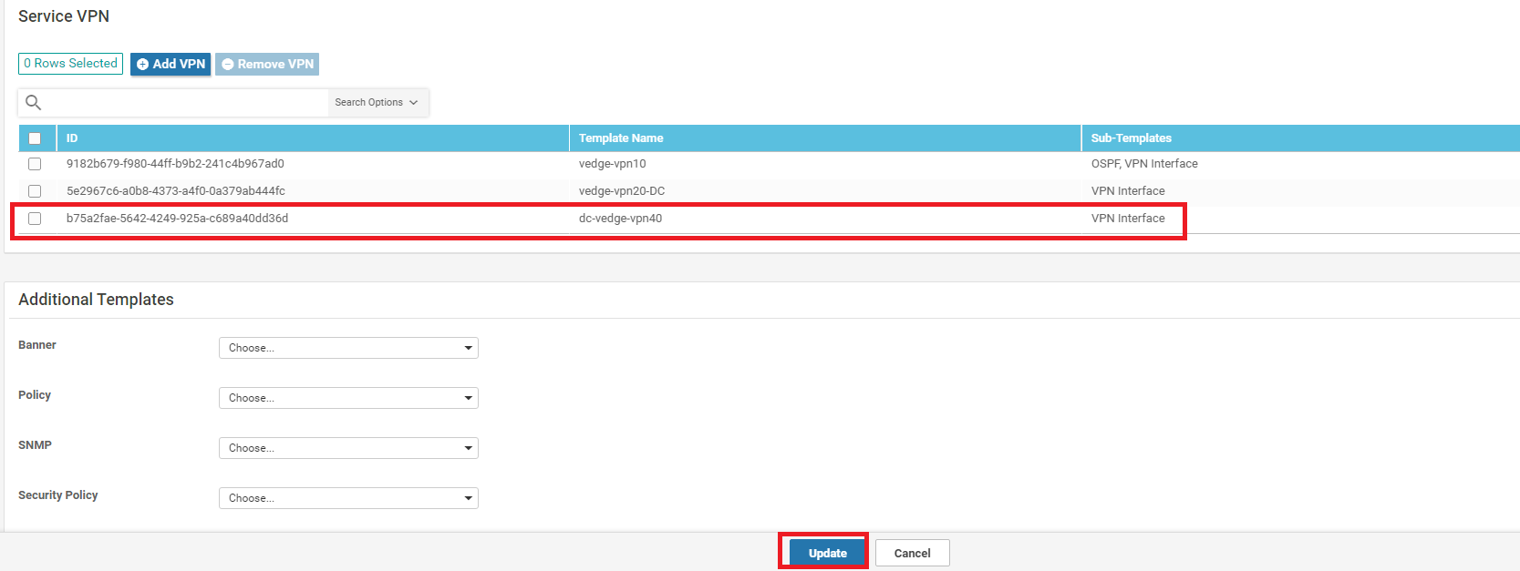
Make sure the Service VPN section shows the addition of the VPN 40 Template and click on Update
-
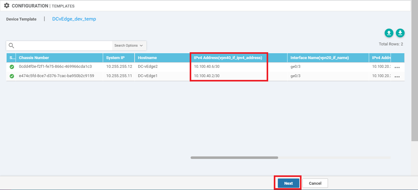
Enter the IPv4 Address field for vpn40_if_ipv4_address as 10.100.40.2/30 (for DC-vEdge1) and 10.100.40.6/30 (for DC-vEdge2). Click on Next
-
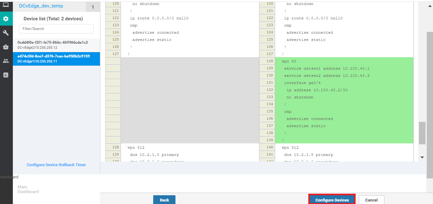
Click on Configure Devices. You can choose to view the side by side configuration, if required, noting the addition of vpn 40 with the corresponding service addresses
-
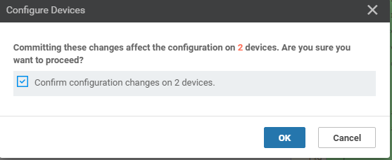
Confirm the configuration change by clicking on the check box and clicking on OK
-
Once the configuration update goes through, log in to the CLI of DC-vEdge1 and DC-vEdge2 via Putty and issue the following commands. You should see successful ping responses. Go to the next step if pings fail
On DC-vEdge1 -
ping vpn 40 10.100.40.1On DC-vEdge2 -ping vpn 40 10.100.40.5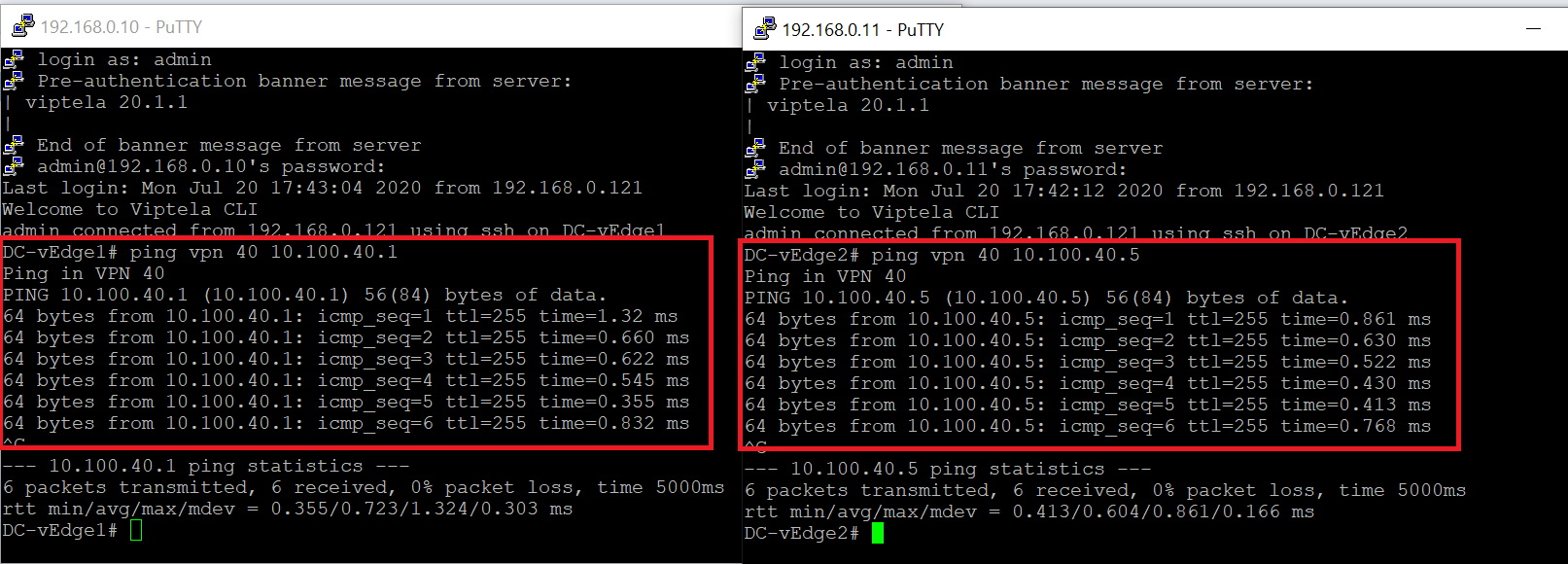
-
If pings fail in the previous step, it’s possible that the mapping of the VM Networks in vCenter needs to be swappped. Log in to vCenter and edit the settings for DC-vEdge1 and DC-vEdge2 such that the network adapters look as below. Try the pings on DC-vEdge1 via
ping vpn 40 10.100.40.1and on DC-vEdge2 viaping vpn 40 10.100.40.5again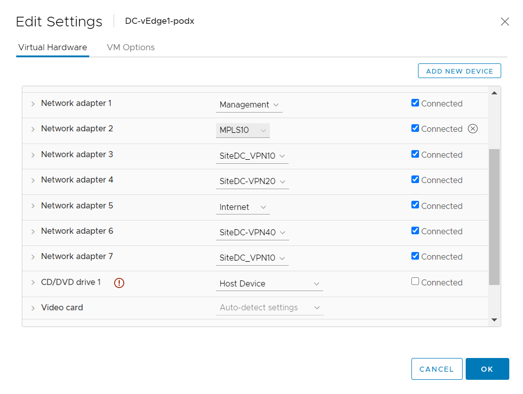
Network Adapters on DC-vEdge1 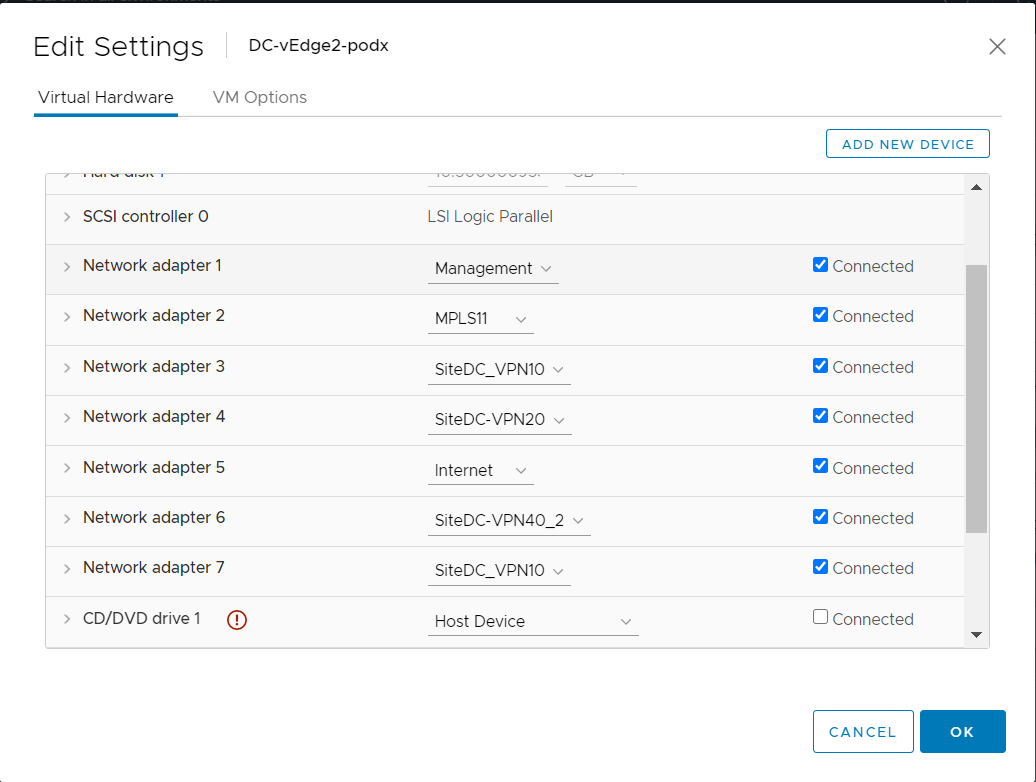
Network Adapters on DC-vEdge2
This completes the configuration needed for adding VPN 40 to the DC-vEdges.
-
-
- Configuration Cleanup and Routing Verification
- Setting up VPN Lists
- Inter VPN Routing Policies
- Inter VPN Routing Verification
- Policies for Service Chaining
- Activity Verification
Configuration Cleanup and Routing Verification
-
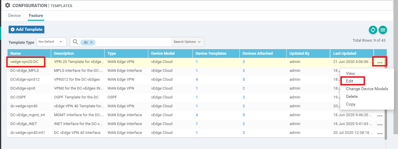
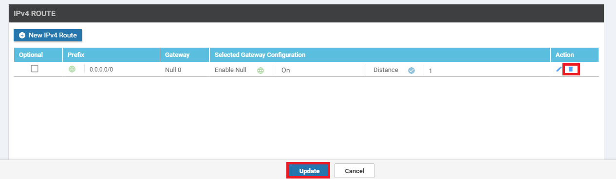
On the vManage GUI, go to Configuration => Templates => Feature Tab. Locate the vedge-vpn20-DC template and click on the three dots next to it. Choose to Edit the template
-
Scroll down to the IPv4 Route section and delete the route populated (it should be a null route) by clicking on the trash icon. Click on Update. Click Next and Configure Devices to push the update out
-
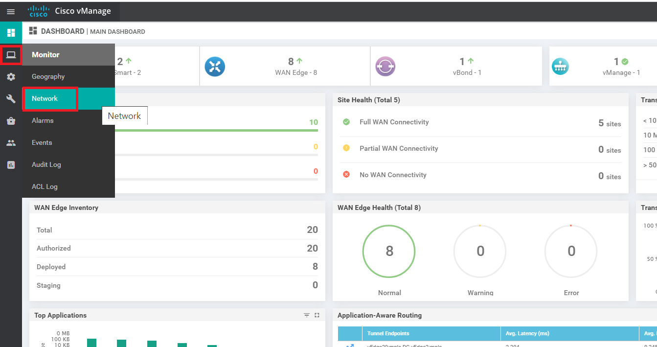
To check the current routing tables for VPN 10 and VPN 20, navigate to Monitor => Network
-
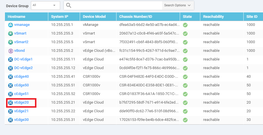
Click on vEdge20
-
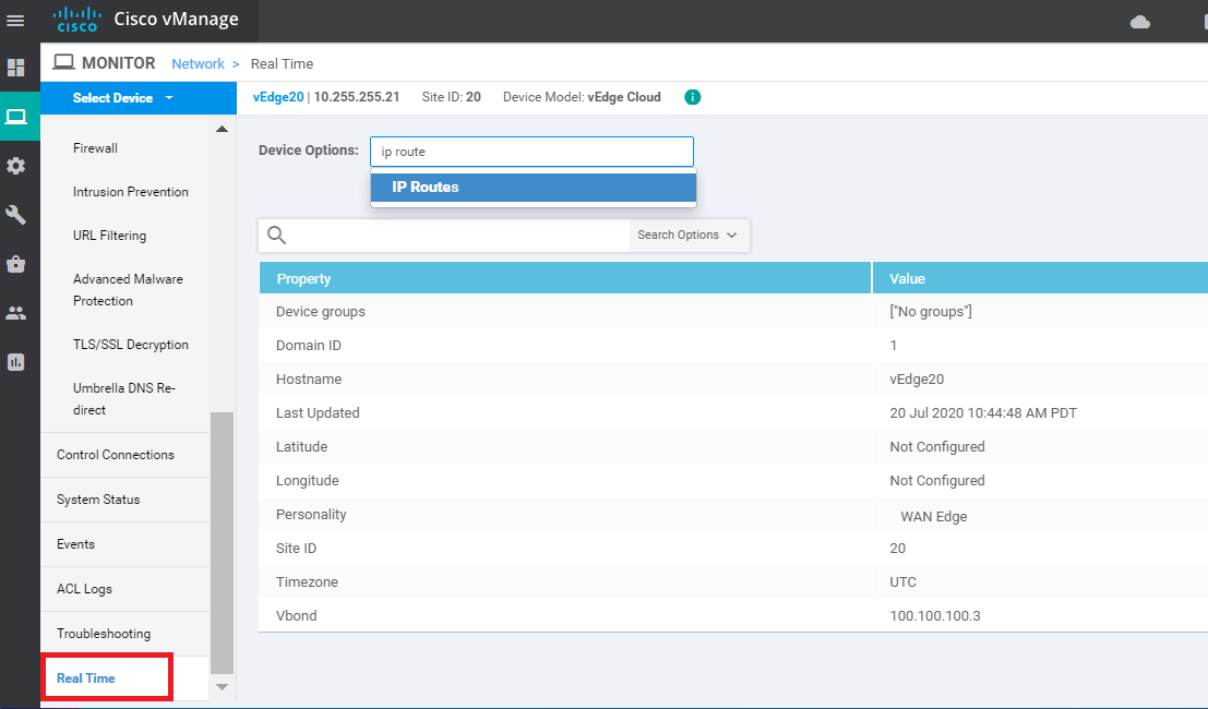
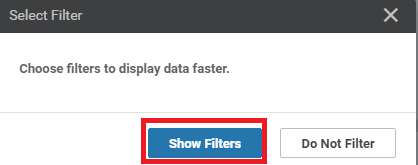
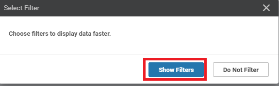
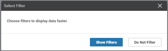
Go to Real Time in the left menu and enter ip route in the Device Options field. Click on IP Routes to see the current routes and choose Show Filters
-
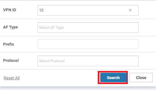
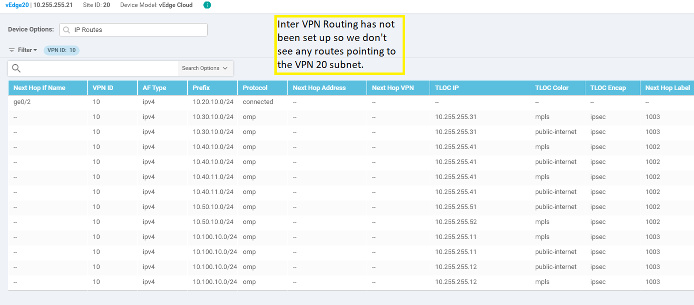
Enter a VPN ID of 10 and click on Search to filter the routes for VPN 10 on vEdge20
-
Since Inter VPN Routing hasn’t been configured yet, we will see routes that are part of VPN 10 only. Subnets from other VPNs will not show up over here. We can thus infer that there won’t be inter VPN connectivity as of now
-
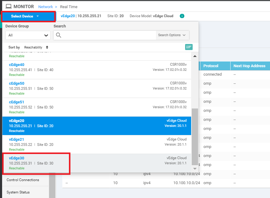
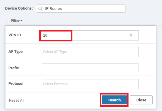
Click on Select Devices (top left-hand corner) and choose vEdge30 from the drop down. Click on Show Filters
-
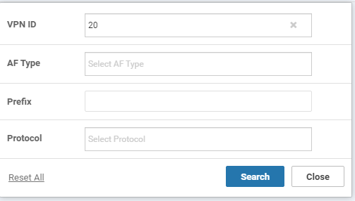
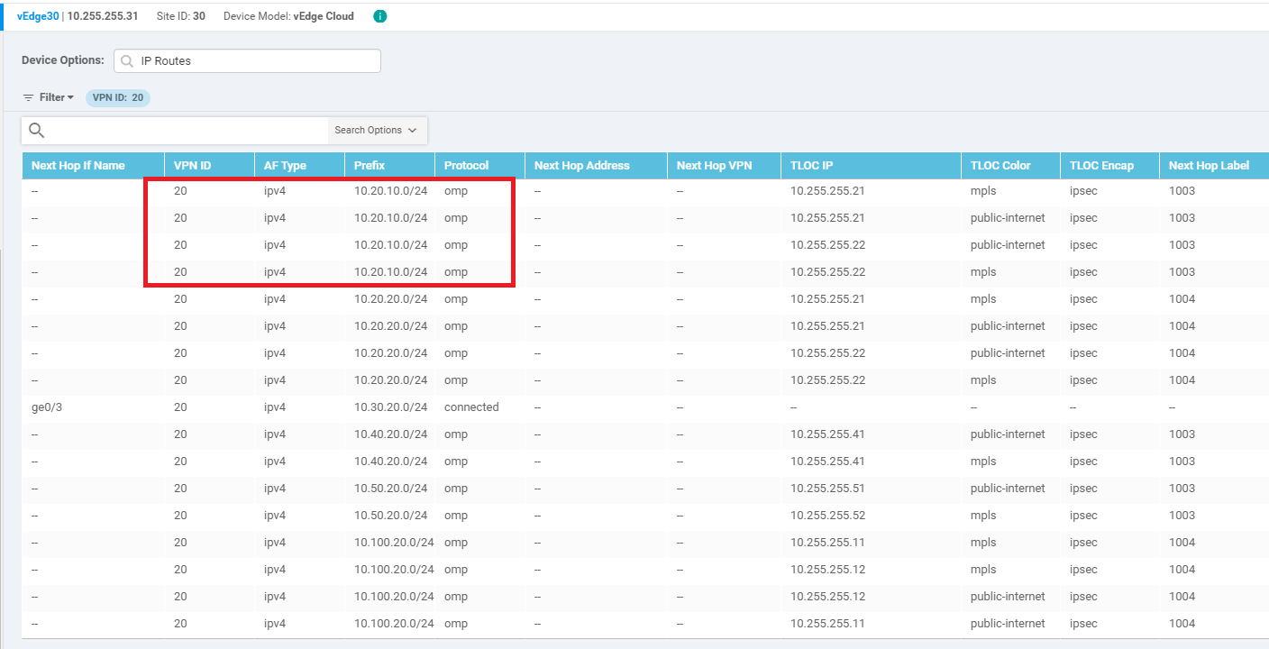
Enter 20 in the VPN ID and click on Search
-
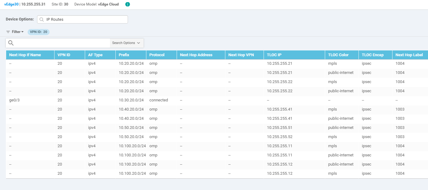
This shows all the routes learnt by vEdge30 in VPN 20. There aren’t any routes subnets in other VPNs, as of now
-
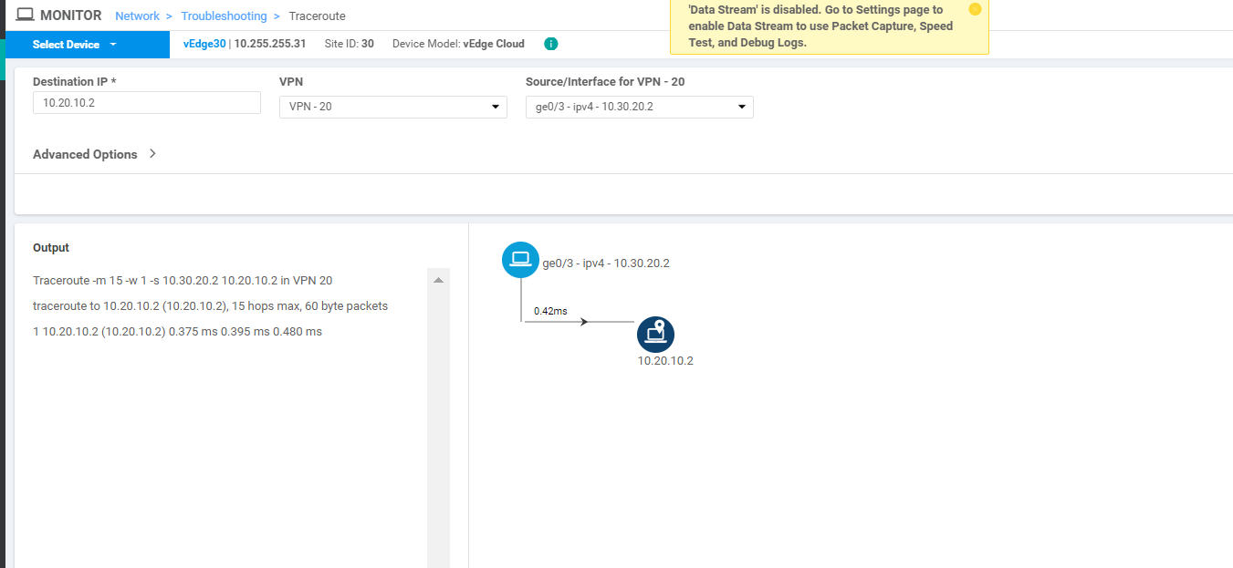
On the left hand slide, click on Troubleshooting and select Traceroute (note that this is being done on vEdge30)
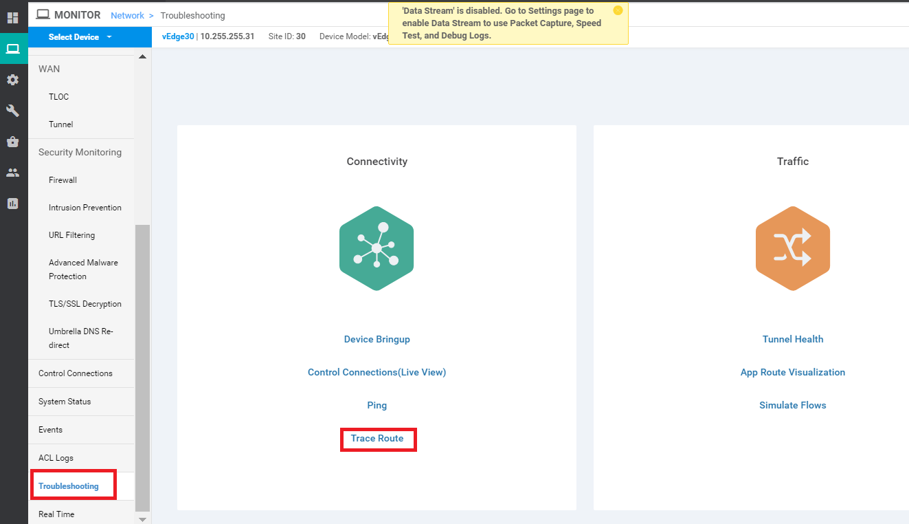
-
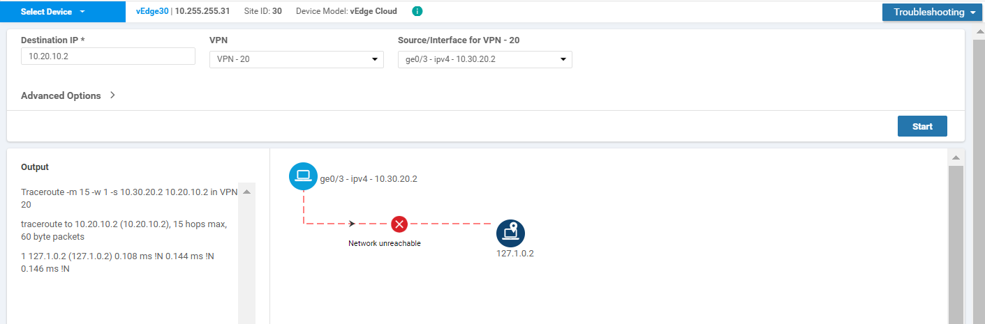
Enter a Destination IP of 10.20.10.2 and select VPN 20 from the VPN drop down. Populate the Source/Interface as ge0/3 and click on Start
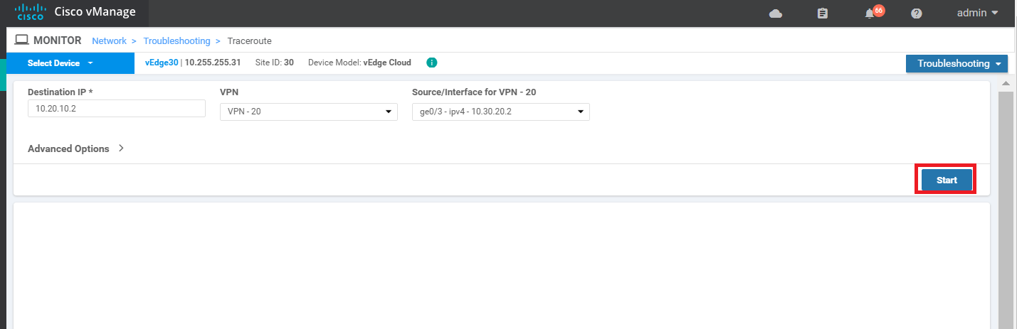
-
As expected, the traceroute should fail
-
Click on Select Device in the top left-hand corner and choose vEdge20. Run the traceroute again, changing the Destination IP to 10.30.20.2, VPN to VPN 10 and the Source/Interface to ge0/2. Click on Start and this should fail as well
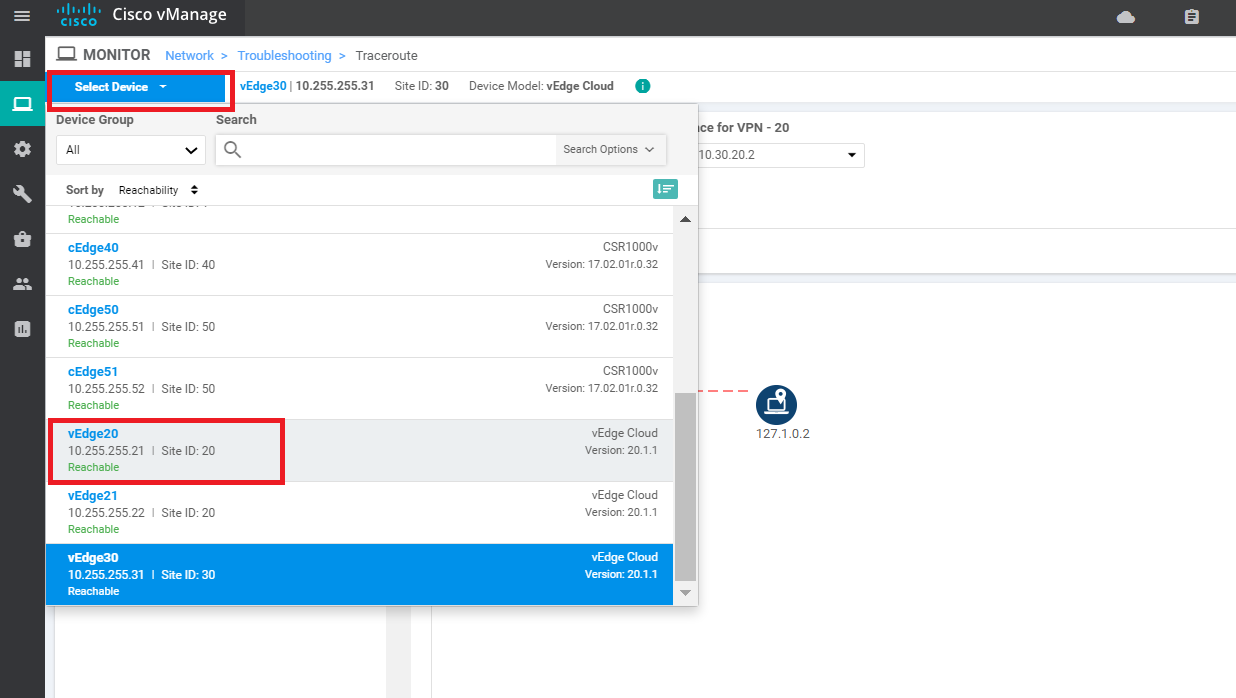
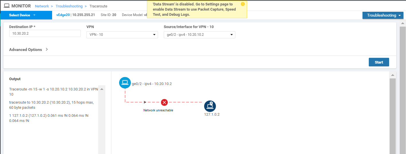
We have established that Inter VPN communication is not happening between Site 20 and Site 30 as of now.
-
-
-
- Setting up VPN Lists
- Inter VPN Routing Policies
- Inter VPN Routing Verification
- Policies for Service Chaining
- Activity Verification
Setting up VPN Lists
In order to facilitate inter VPN connectivity, we will be setting up VPN Lists that can be used in our Policies.
-
On the vManage GUI, go to Configuration => Policies
-
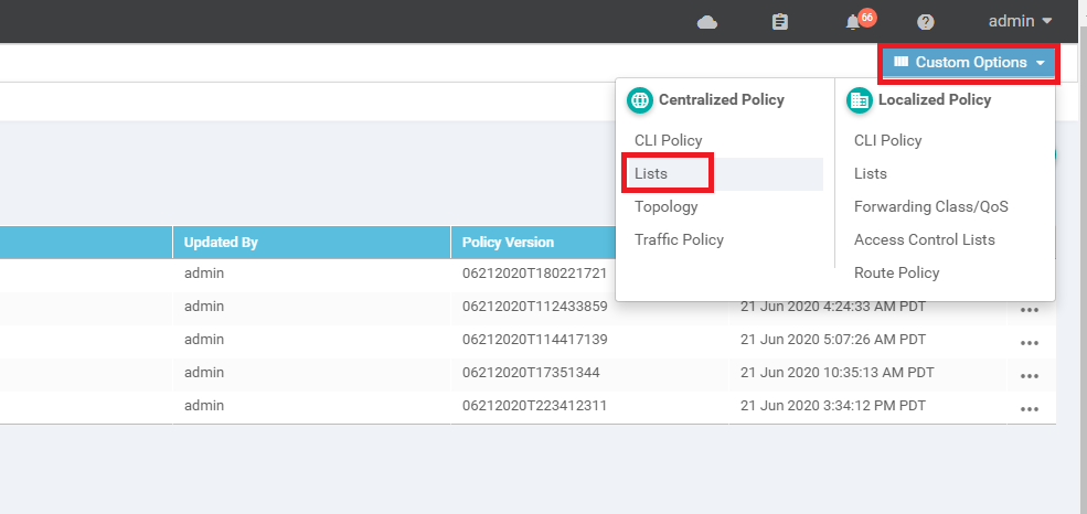
Click on Custom Options in the top right-hand corner and click on Lists (under Centralized Policy)
-
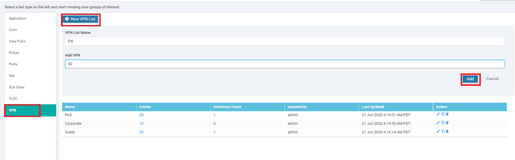
Select VPN and click on New VPN List. Enter a VPN List Name of FW and put 40 for the Add VPN field. Click on Add
-
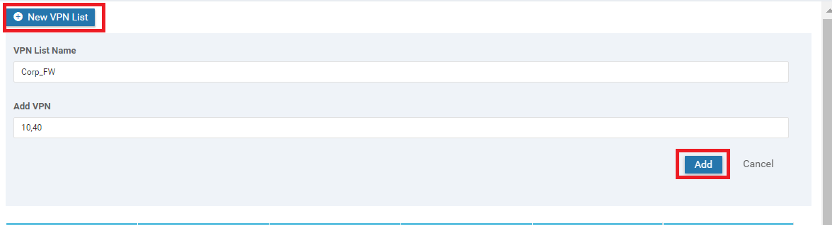
Click on New VPN List again and Put a VPN List Name of Corp_FW. Put 10,40 in the Add VPN field. Click on Add
-
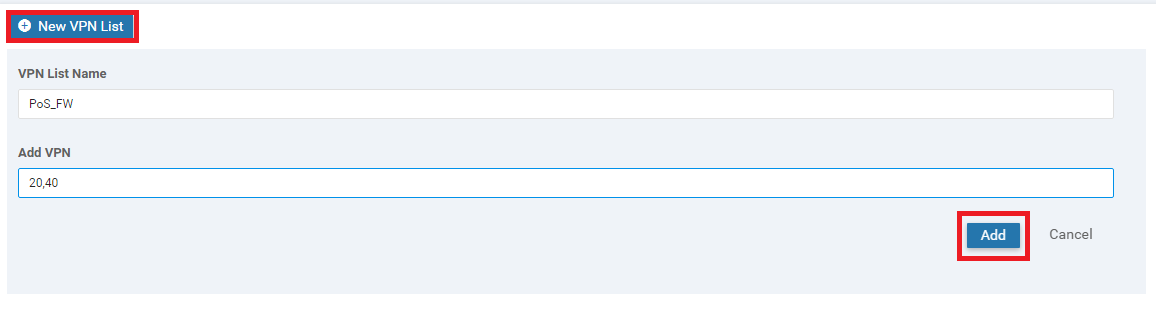
Click on New VPN List again and Put a VPN List Name of PoS_FW. Put 20,40 in the Add VPN field. Click on Add
-
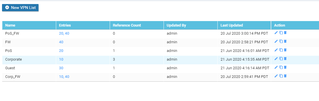
Make sure that the following VPN lists show up, before proceeding
-
-
-
-
- Inter VPN Routing Policies
- Inter VPN Routing Verification
- Policies for Service Chaining
- Activity Verification
Inter VPN Routing Policies
-
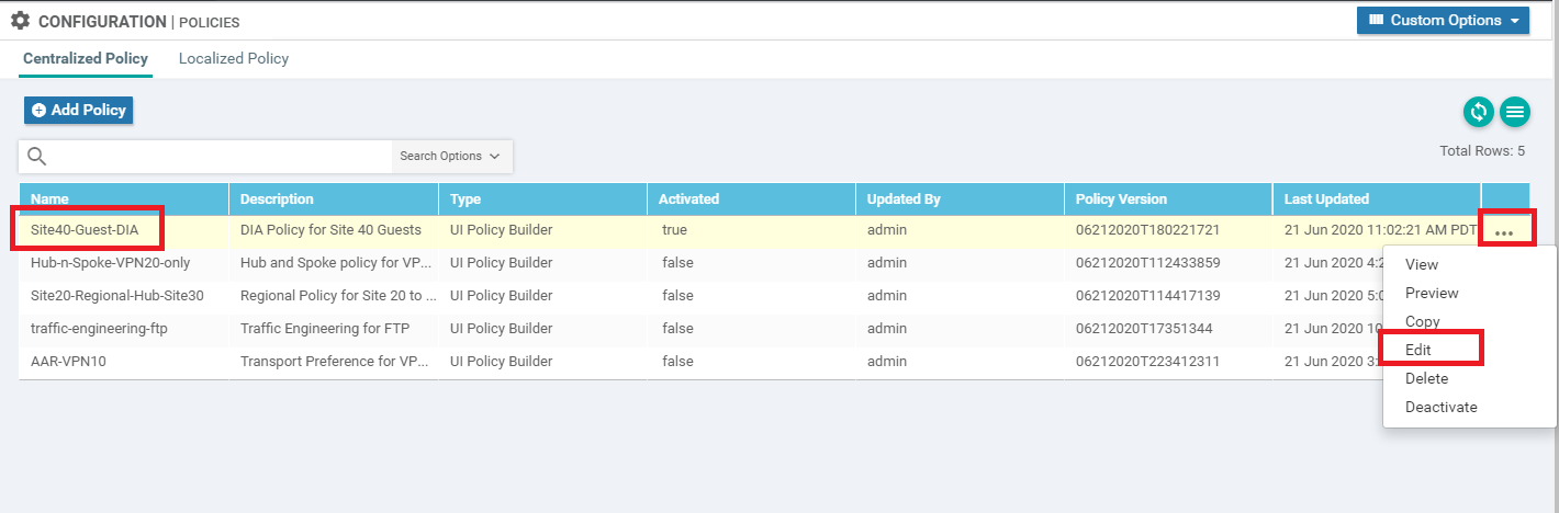
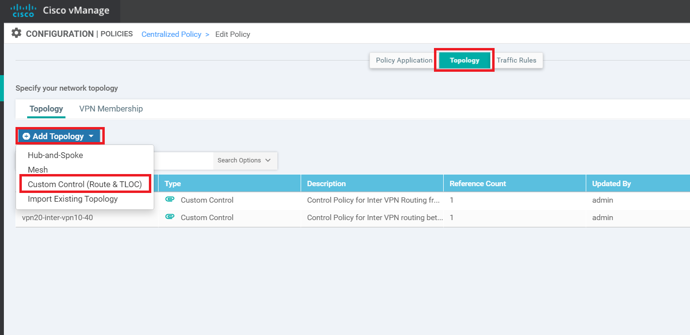
Navigate to Configuration => Policies and locate the Site40-Guest-DIA Policy. Click on the three dots next to it and choose to Edit the policy
-
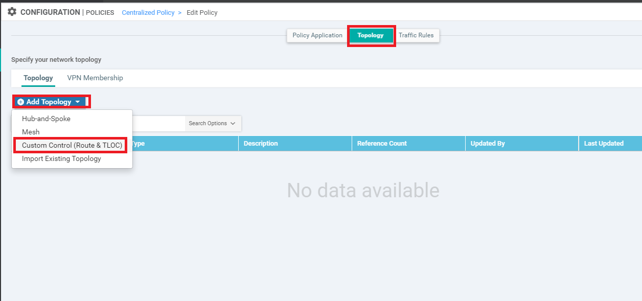
Click on the Topology tab (top of the screen) and click on Add Topology. Choose to add a Custom Control (Route & TLOC) policy
-
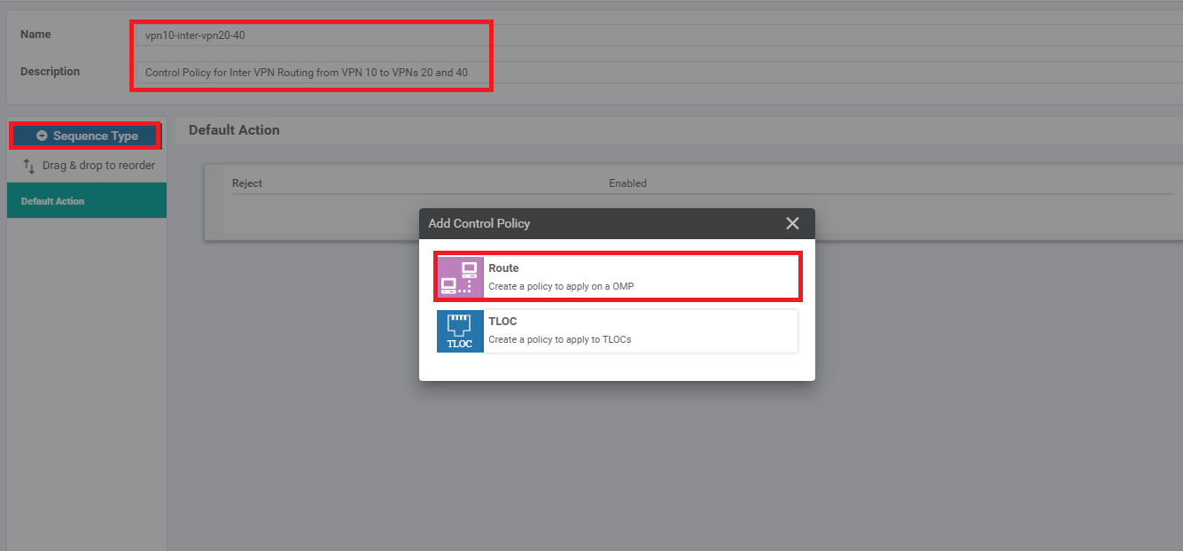
Give the policy a Name of vpn10-inter-vpn20-40 with a Description of Control Policy for Inter VPN Routing from VPN 10 to VPNs 20 and 40. Click on Sequence Type and choose Route
-
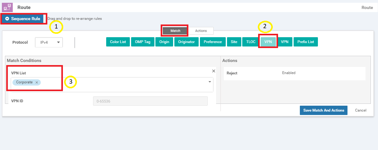
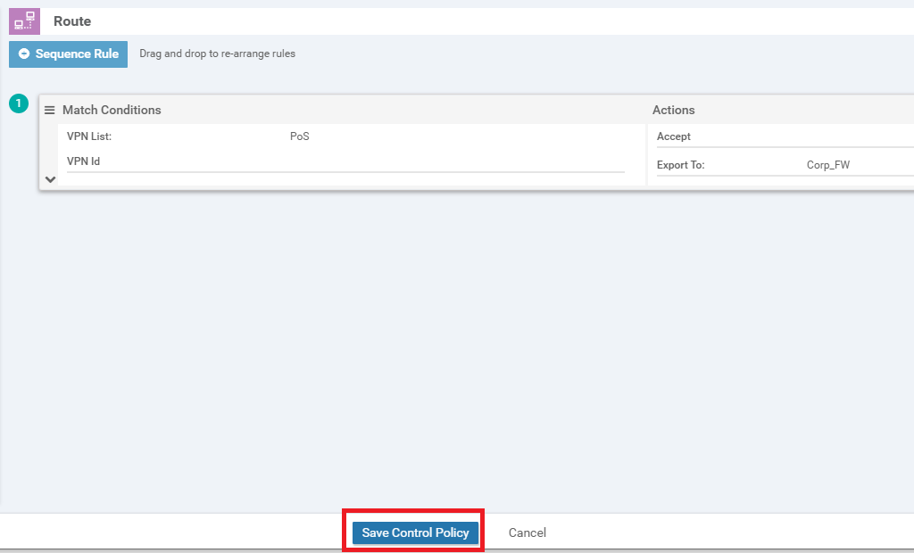
Click on Sequence Rule and add a VPN match. Select Corporate from the VPN List drop down
-
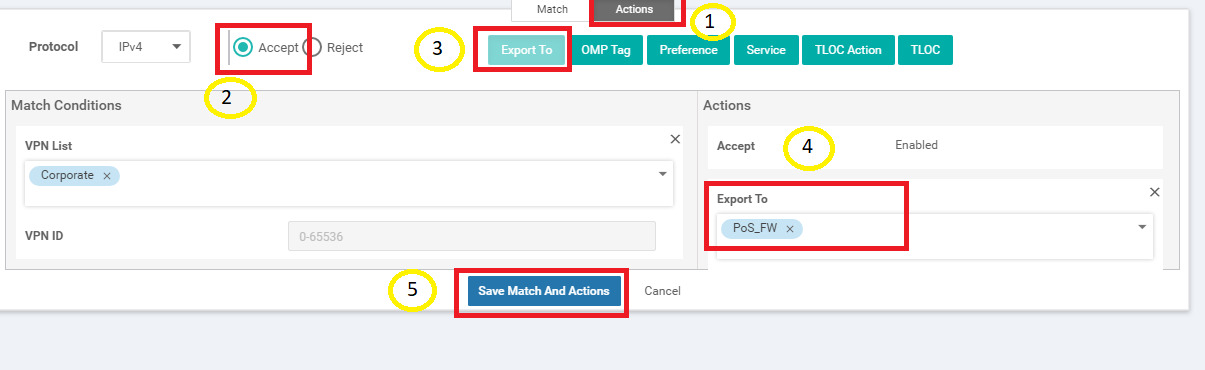
Click on the Actions tab and select the Accept radio button. Click on Export To and select PoS_FW from the drop down under Actions. Click on Save Match And Actions
-
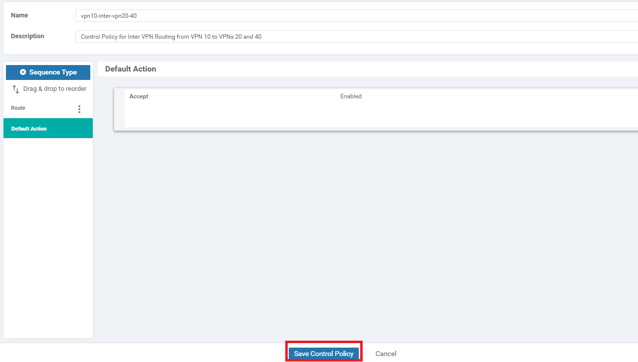
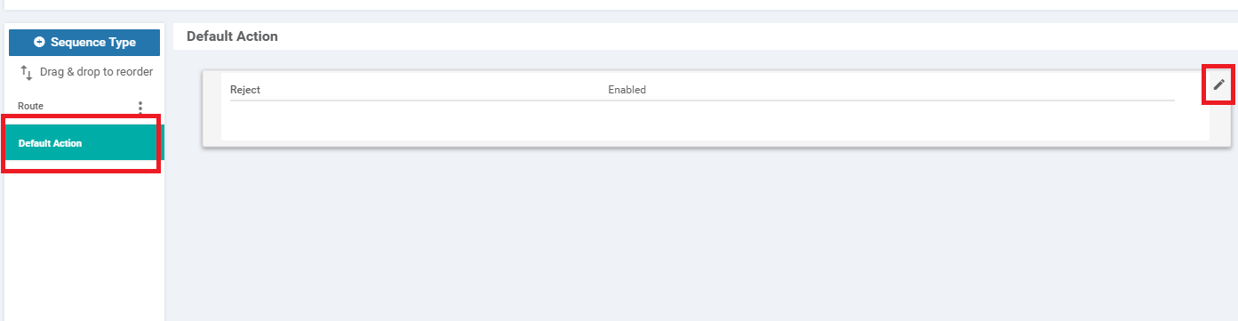
Select Default Action on the left-hand side and click on the pencil icon to edit the Default Action
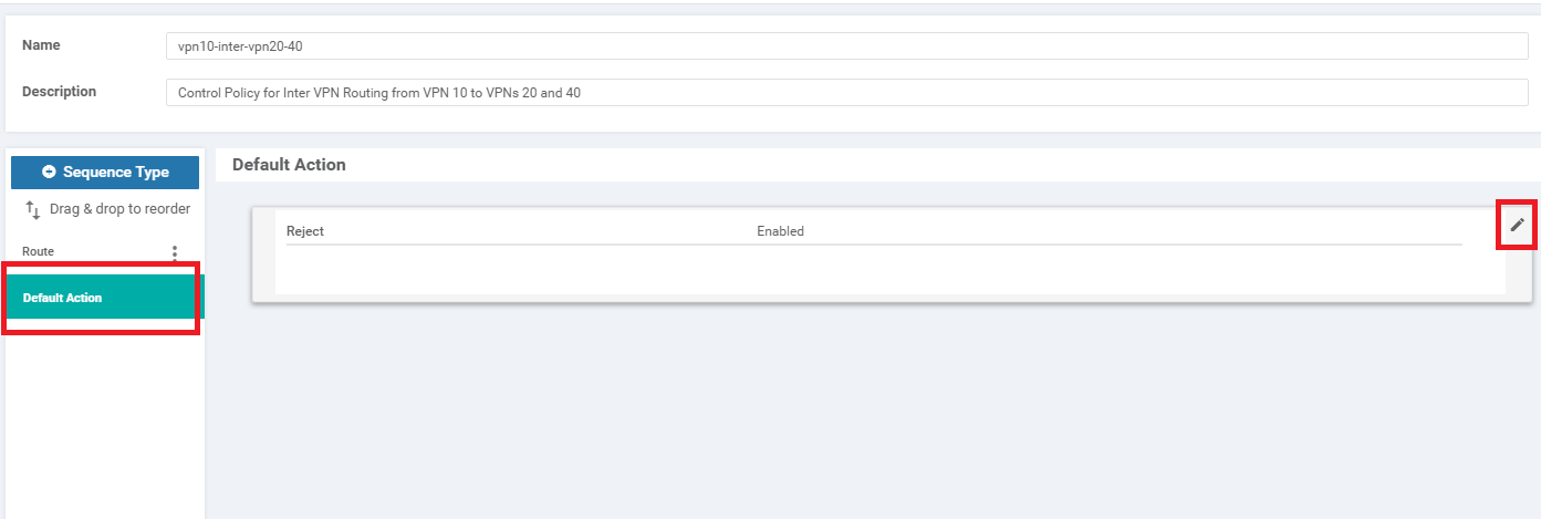
-
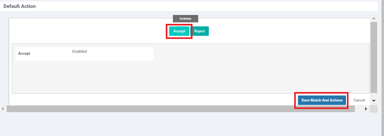
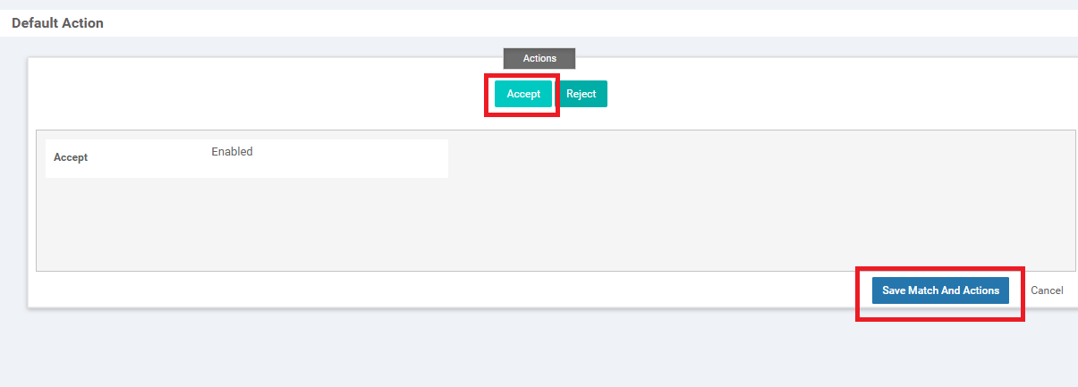
Click on Accept and then Save Match And Actions

-
Click Save Control Policy
-
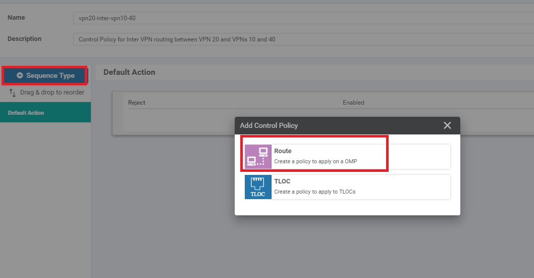
Click on Add Topology and add another Custom Control (Route & TLOC) policy. Give it a Name of vpn20-inter-vpn10-40 with a Description of Control Policy for Inter VPN routing between VPN 20 and VPNs 10 and 40. Click on Sequence Type and select Route
-
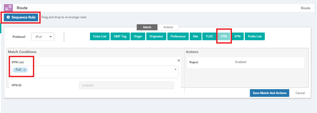
Click on Sequence Rule and select VPN as the match. Select PoS from the VPN List
-
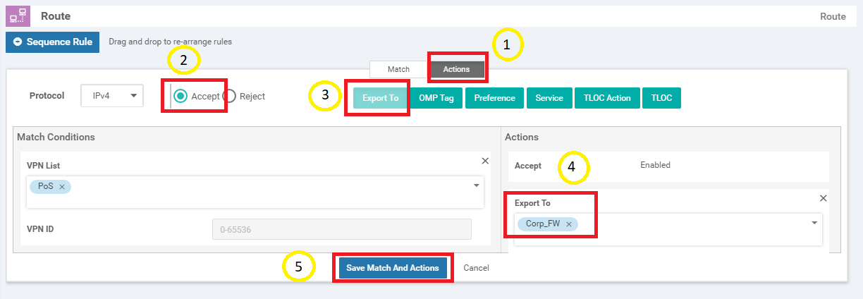
Click on the Actions tab and select the Accept radio button. Click on Export To and select the Corp_FW VPN list in the Export To drop down under Actions. To save the rule, click on Save Match And Actions
-
Click on Default Action on the left-hand side and click the Pencil icon to edit the Default Action
-
Select Accept and click Save Match And Actions
-
Click on Save Control Policy
-
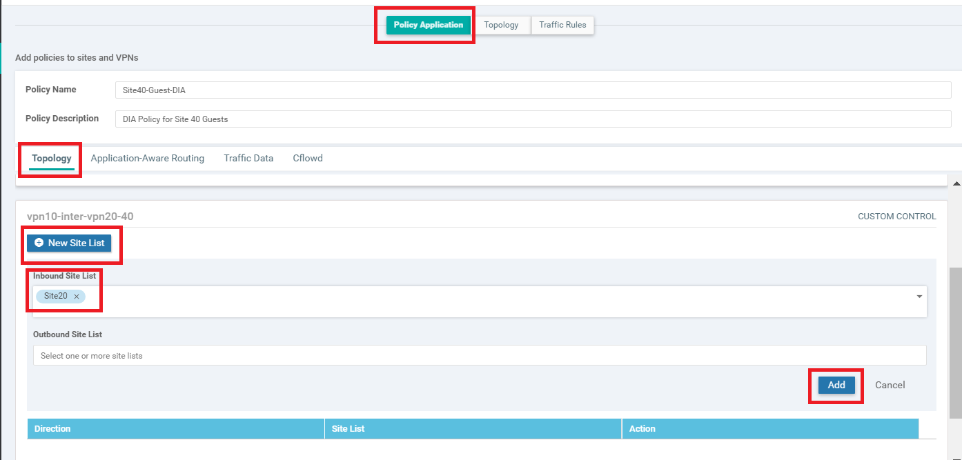
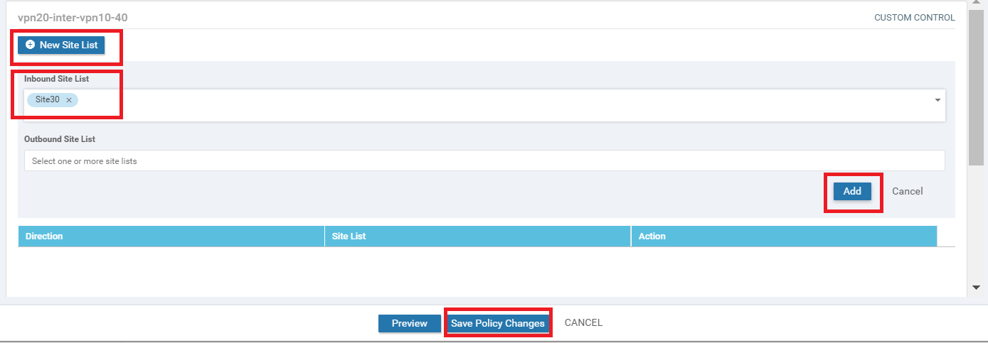
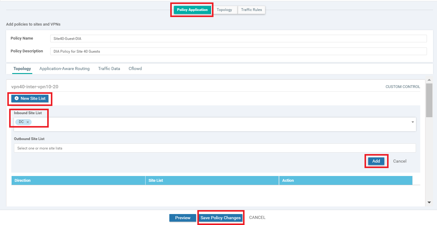
You should be back at the main policy screen. Click on the Policy Application tab and make sure you’re under the Topology sub-tab (should not be under the main Topology tab). Click on New Site List under the entry for vpn10-inter-vpn20-40 and select the Inbound Site List as Site20. Click on Add
-
Click on New Site List under the entry for vpn20-inter-vpn10-40 and select the Inbound Site List as Site30. Click on Add. Click on Save Policy Changes
-
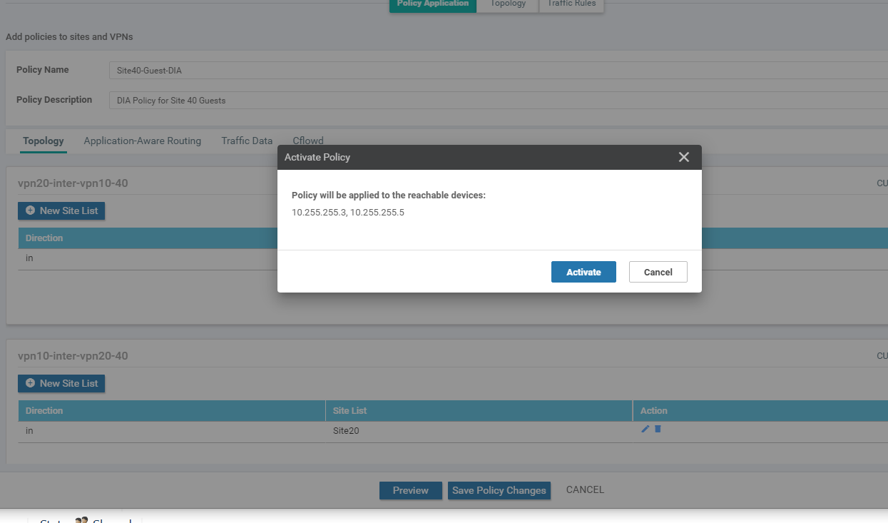
Click on Activate to push the changes to the vSmarts
We have set up the policies for Inter VPN Routing.
-
-
-
-
-
- Inter VPN Routing Verification
- Policies for Service Chaining
- Activity Verification
Inter VPN Routing Verification
-
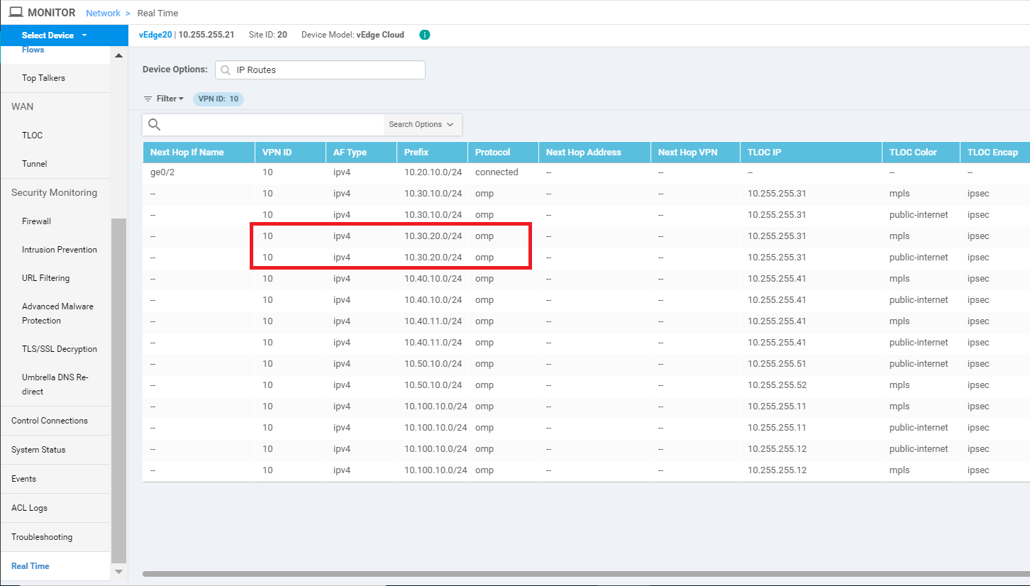
On the vManage GUI, navigate to Monitor => Network and click on vEdge20. Scroll down along the left-hand side menu and click on Real Time. Enter IP Routes in the Device Options and select IP Routes when it pops up. Choose Show Filters and enter a VPN ID of 10. Click on Search. The Routing Table for VPN 10 on vEdge20 should show routes to subnets at Site 30 VPN 20
-
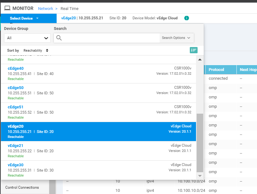
Click on Select Device in the top left-hand corner and click on vEdge30
-
Click Show Filters and enter a VPN ID of 20. Click on Search
-
You should see routes for Site 20 VPN 10
-
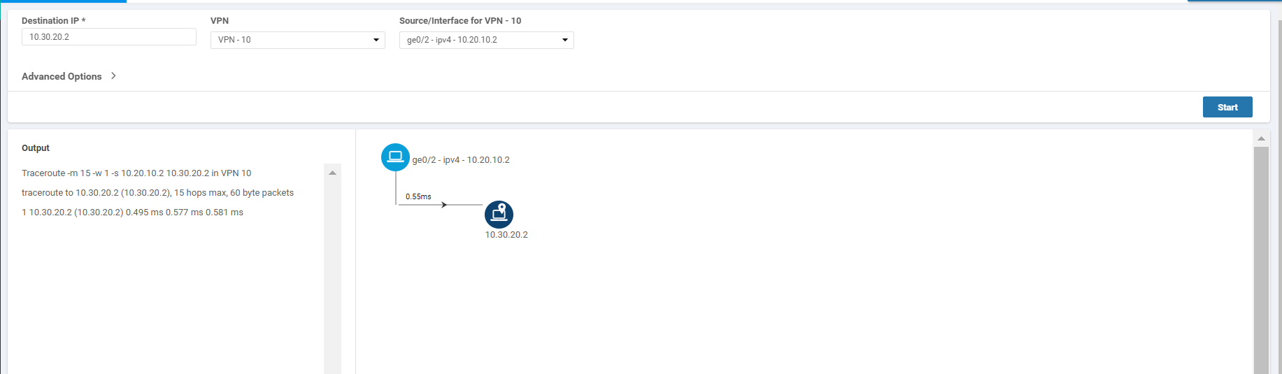
Click on Troubleshooting on the left-hand side and make sure you have vEdge20 as the selected device. Enter a Destination IP of 10.30.20.2 with a VPN of VPN - 10. Select a Source/Interface of ge0/2 (once again, verify that you’re at the vEdge20 device. If not, click on the Select Device drop down from the top left-hand corner and select vEdge20). Click on Start. Notice that we now have direct Inter VPN connectivity from Site 20 VPN 10 to Site 30 VPN 20
-
Click on Select Device in the top left-hand corner and select vEdge30. Enter a Destination IP of 10.20.10.2 with a VPN of VPN - 20 and a Source/Interface of ge0/3. Click on Start. Notice that we now have direct Inter VPN Connectivity from Site 30 VPN 20 to Site 20 VPN 10
This completes the verification of our Inter VPN Routing configuration.
-
-
-
-
-
-
- Policies for Service Chaining
- Activity Verification
Policies for Service Chaining
Direct connectivity between two VPNs might not be a desirable scenario. There might be a requirement to enforce certain rules when two VPNs are communicating with each other. That’s where Service Chaining comes into the picture, where we route Inter VPN traffic through an intermediary device (like a Firewall) to enforce our policies/rules. To reiterate, the traffic flow should look like the diagram below at the end of this section vs. the direct connectivity that we have between VPNs right now.
The Black arrow between Site 20 and Site 30 indicates the traffic flow when Inter VPN Routing configuration is done for the first time. Traffic flows directly between the two Sites.
The Orange arrow is the traffic flow from Site 20 VPN 10 to Site 30 VPN 20 once Service Chaining is configured.
Source IP: 10.20.10.2 or 10.20.10.3
Destination IP: 10.30.20.2
The Green arrow is the traffic flow from Site 30 VPN 20 to Site 20 VPN 10 once Service Chaining is configured.
Source IP: 10.30.20.2
Destination IP: 10.20.10.2 or 10.20.10.3
-
On the vManage GUI, go to Configuration => Policies. Locate the Site40-Guest-DIA policy and click on the three dots next to it. Choose to Edit the policy. Make sure you’re on the Topology tab and click on Add Topology. Choose to add a Custom Control (Route and TLOC) topology
-
Give the Custom Control Policy a Name of site20-fw-site30 and a Description of Traffic from Site 20 to Site 30 via the Firewall. Click on Sequence Type and choose Route
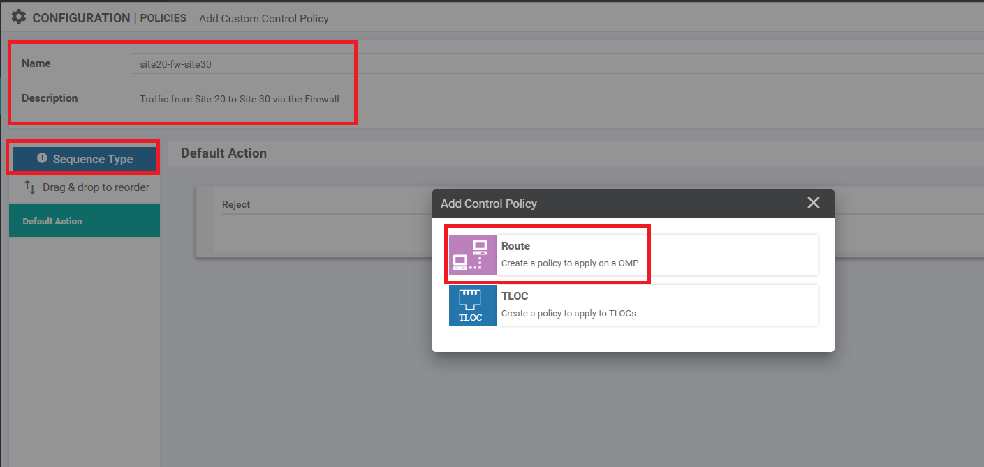
-
Click on Sequence Rule and select Site for a Match Condition. Click on the Site List drop down and choose Site 30. Click on the Actions tab
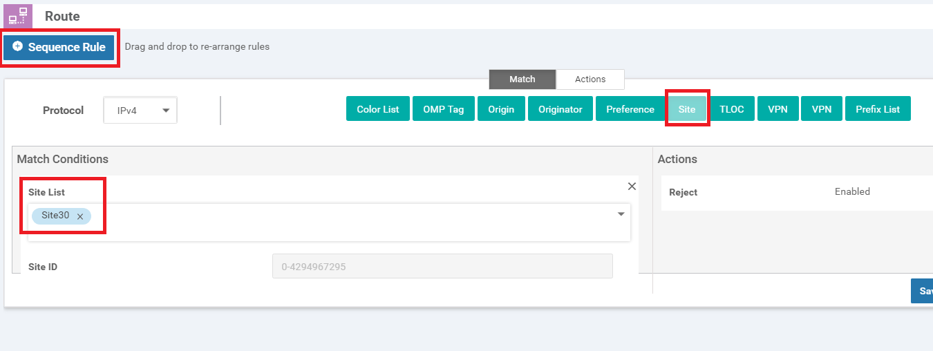
-
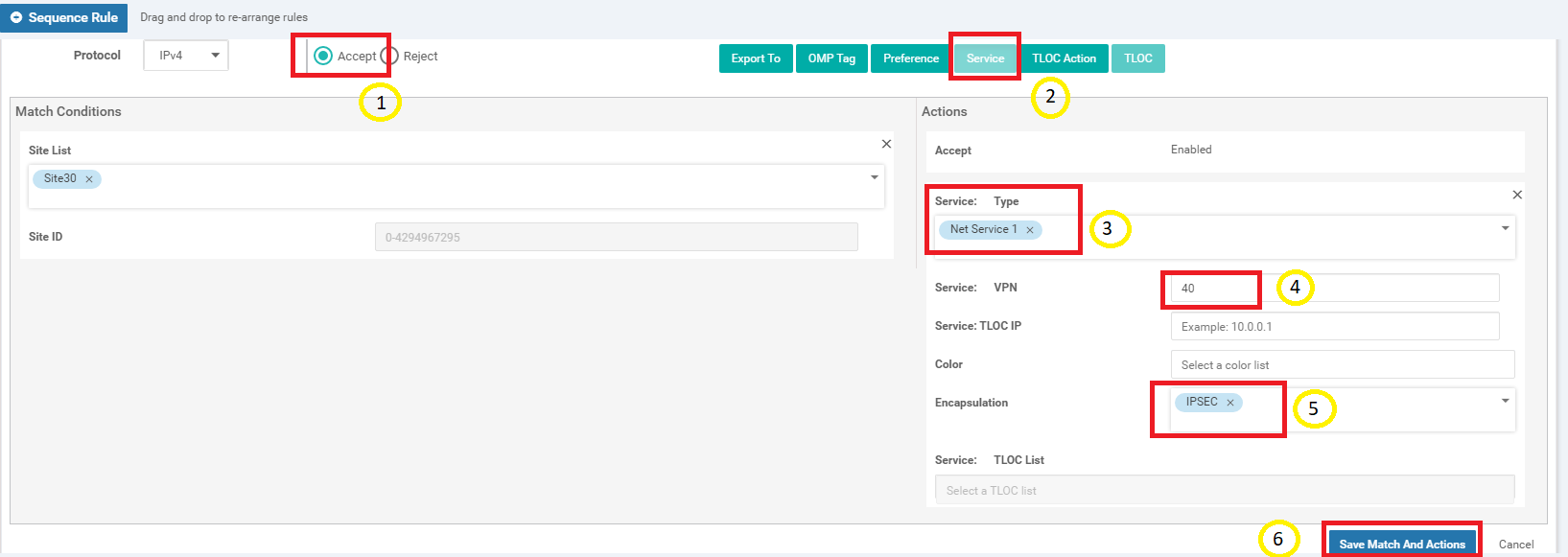
Select the Accept radio button and choose Service. Under Actions select the Service: Type as Net Service 1 and specify a Service: VPN of 40. Select an Encapsulation of IPSEC and click on Save Match And Actions to save this rule
-
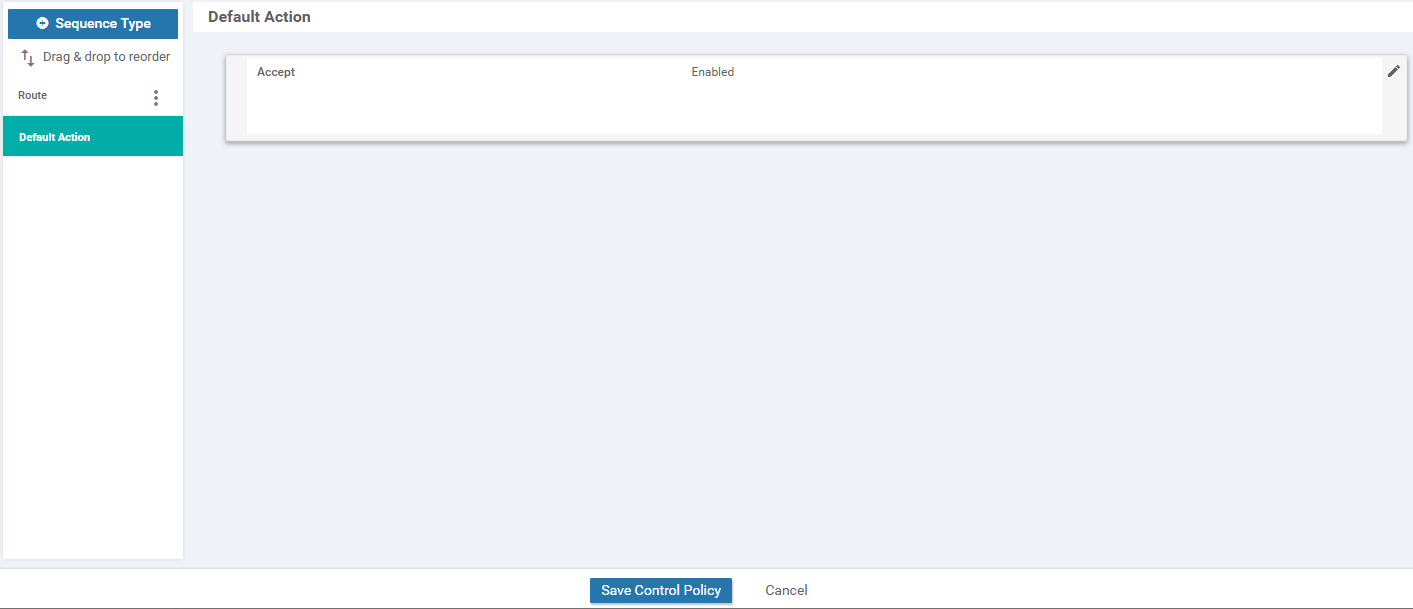
Click on Default Action on the left-hand side and click the pencil icon. Select Accept and then Save Match And Actions. The Default Action should change to Accept Enabled. Click on Save Control Policy
-
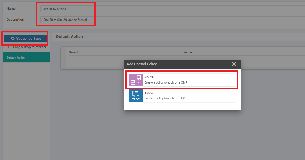
Make sure you’re on the Topology tab and click on Add Topology. Choose to add a Custom Control (Route and TLOC) topology. Give the Custom Control Policy a Name of site30-fw-site20 and a Description of Site 30 to Site 20 via the firewall. Click on Sequence Type and choose Route
-
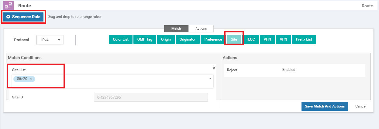
Click on Sequence Rule and then select Site. Choose Site 20 in the Site List under Match Conditions. Click on Actions
-
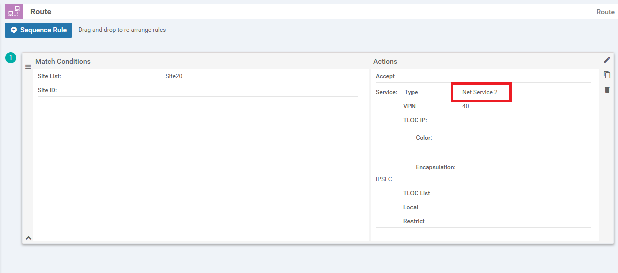
Select the Accept radio button and choose Service. Under Actions select the Service: Type as Net Service 2 and specify a Service: VPN of 40. Select an Encapsulation of IPSEC and click on Save Match And Actions to save this rule
-
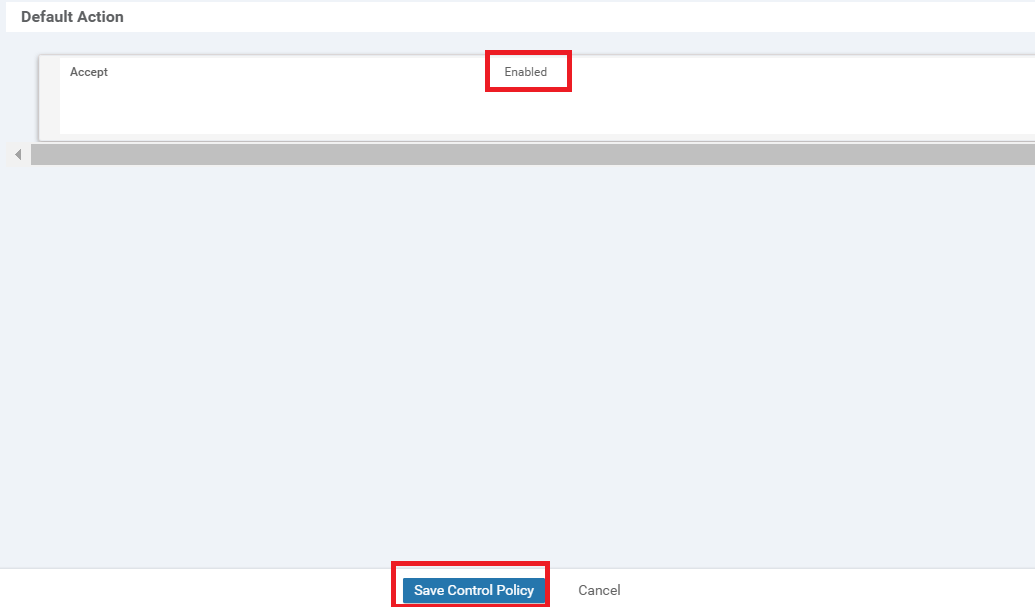
Click on Default Action on the left-hand side and click the pencil icon. Select Accept and then Save Match And Actions. The Default Action should change to Accept Enabled. Click on Save Control Policy
-
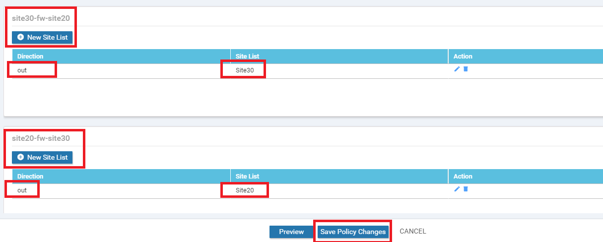
Go to the Policy Application tab and locate the site30-fw-site20 and site20-fw-site30 entries. For site30-fw-site20, click on New Site List and choose Site30 in the out direction. Click on Add. Similarly, for site20-fw-site30, click on New Site List and choose Site20 in the out direction. Click on Add. Click on Save Policy Changes. Activate the change when prompted to do so
-
-
-
-
-
-
-
- Activity Verification
Activity Verification
-
(Optional) Log in to the CLI of vEdge20 via Putty (username and password given below) and enter
ping vpn 10 10.100.40.2to test connectivity between Site 20 VPN 10 and Site DC VPN 40. The pings should failUsername Password admin admin 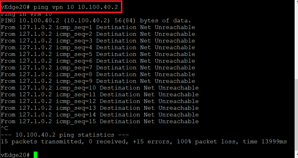
This is due to the fact that we haven’t set up inter VPN connectivity from VPN 10/20 to VPN 40. However, as long as VPN 40 can get to VPN 10/20 routes, Service Chaining should work.
-
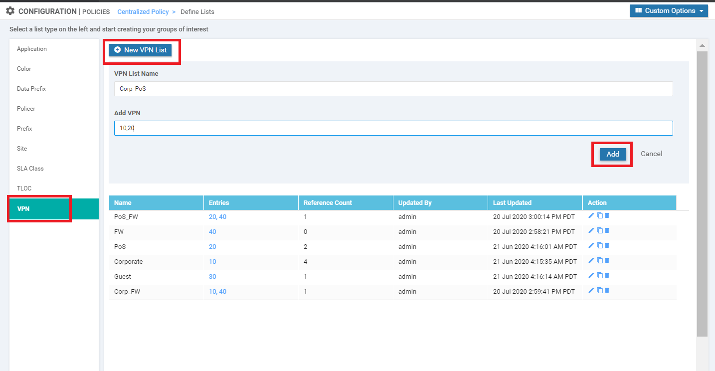
(Optional) On the vManage GUI, navigate to Configuration => Policies. Click on Custom Options on the top right-hand corner and select Lists (under Centralized Policy). Click on VPN in the left-hand menu and then New VPN List. Enter a VPN List Name of Corp_PoS and put 10,20 in the Add VPN field. Click on Add
-
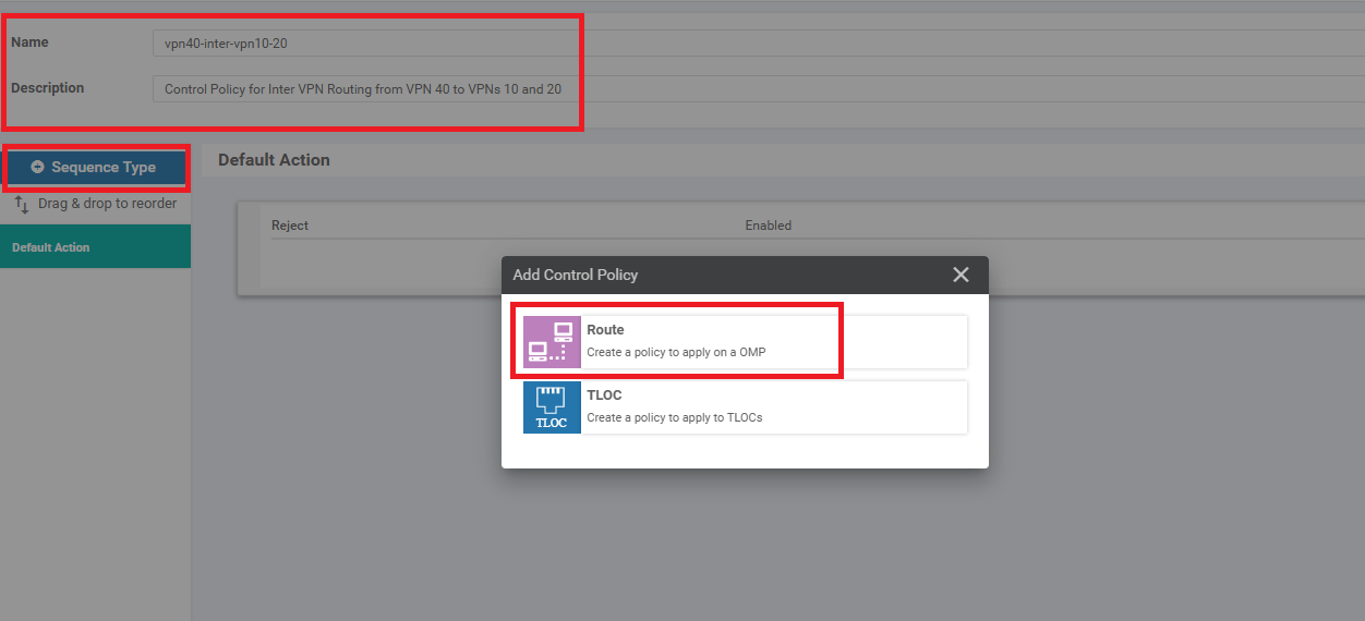
(Optional) Go to Configuration => Policies and locate the Site40-Guest-DIA Policy. Click on the three dots next to it and choose to Edit the policy. Click on the Topology tab (top of the screen) and click on Add Topology. Choose to add a Custom Control (Route & TLOC) policy. Give the policy a Name of vpn40-inter-vpn10-20 with a Description of Control Policy for Inter VPN Routing from VPN 40 to VPNs 10 and 20. Click on Sequence Type and choose Route
-
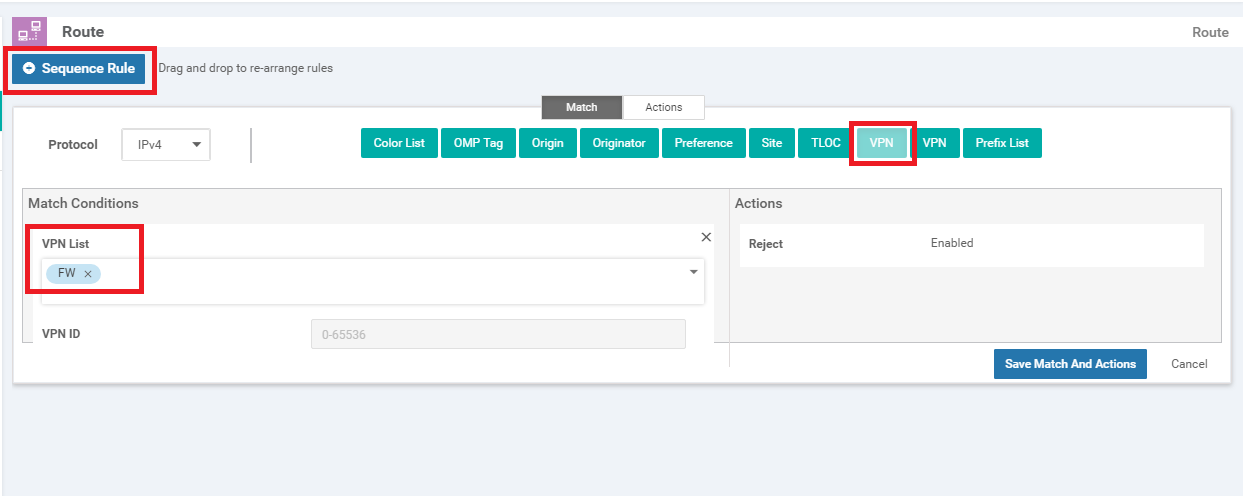
(Optional) Click on Sequence Rule and add a VPN match. Select FW from the VPN List drop down
-
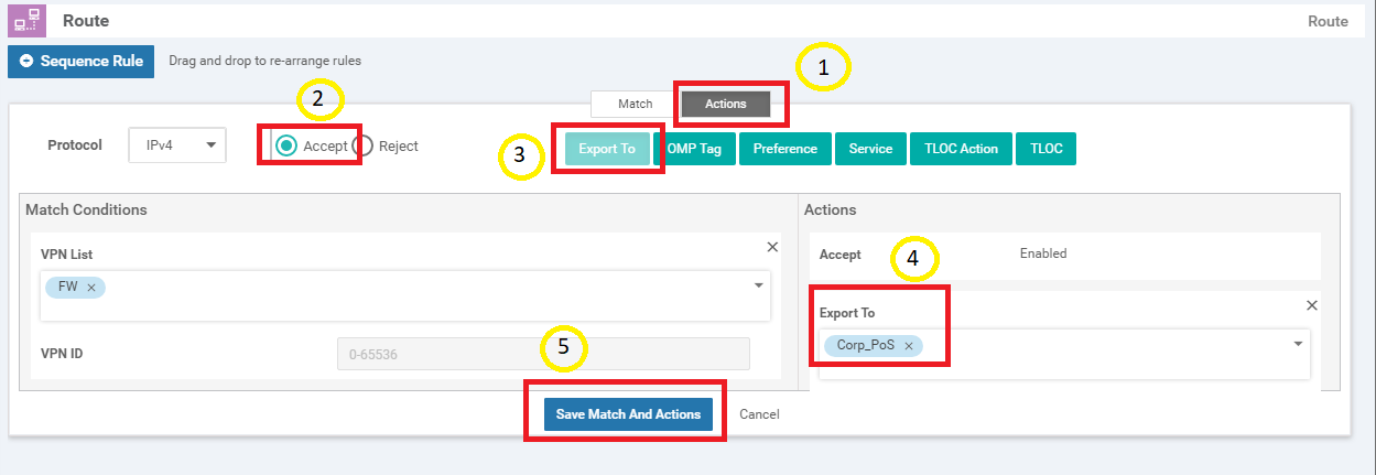
(Optional) Click on the Actions tab and select the Accept radio button. Click on Export To and select Corp_PoS from the drop down under Actions. Click on Save Match And Actions
-
(Optional) Select Default Action on the left-hand side and click on the pencil icon to edit the Default Action. Click on Accept and then Save Match And Actions. Click Save Control Policy
-
(Optional) You should be back at the main policy screen. Click on the Policy Application tab and make sure you’re under the Topology sub-tab (should not be under the main Topology tab). Click on New Site List under the entry for vpn40-inter-vpn10-20 and select the Inbound Site List as DC. Click on Add. Click on Save Policy Changes. Click on Activate to push the changes to the vSmarts
-
(Optional) Head back over to the CLI of vEdge20 and type
ping vpn 10 10.100.40.2. The pings should now be successful. Typeping vpn 10 10.100.40.1to ping the Firewall. This should also work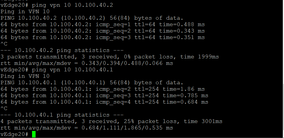
-
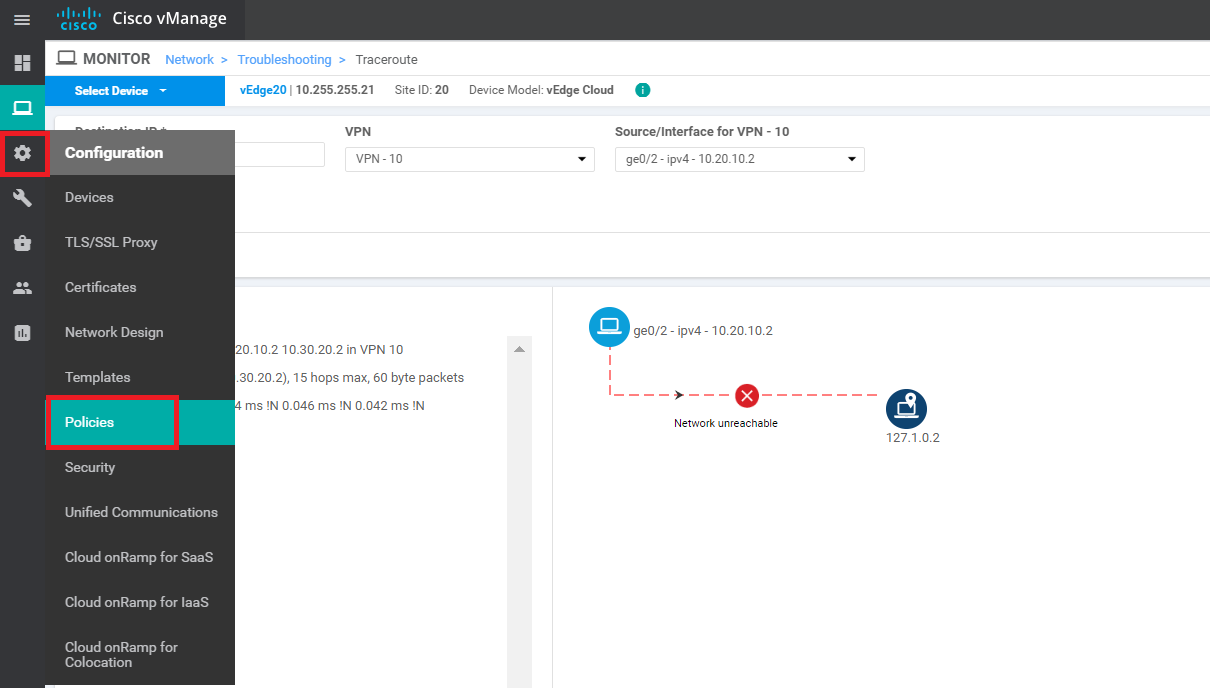
On the vManage GUI, go to Monitor => Network and select vEdge20. Click on Troubleshooting along the left-hand menu and choose Traceroute. Enter a Destination IP of 10.30.20.2 and a VPN of VPN - 10. Set the Source/Interface as ge0/2 and click on Start. We are thus doing a traceroute from Site 20 VPN 10 to Site 30 VPN 20
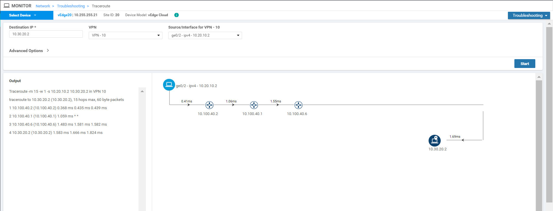
Notice that traffic doesn’t flow directly between the sites. Instead, it traverses the Firewall (IP of 10.100.40.1 in this case) and then goes to Site 30 VPN 20.
-
Click on Select Device in the top left-hand corner and select vEdge30. Enter a Destination IP of 10.20.10.2 and a VPN of VPN - 20. Specify a Source/Interface of ge0/3 and click on Start. We are doing a traceroute from Site 30 VPN 20 to Site 20 VPN 10
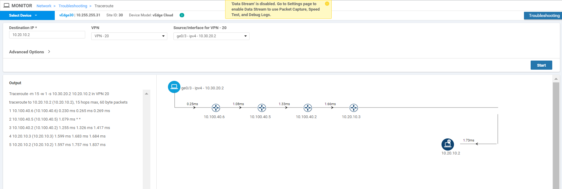
In this case as well, traffic traverses the Firewall (IP of 10.100.40.5) and then goes to Site 20 VPN 10.
This completes the Service Chaining lab activity.