- Creating the DC-vEdge VPN Feature Templates
- Creating the VPN0 Feature Template
- Creating the VPN512 Feature Template
- Creating the INET VPN Interface Feature Template
- Creating the MPLS VPN Interface Feature Template
- Creating the Mgmt VPN Interface Feature Template
- Creating a Device Template and Attaching Devices
- Activity Verification
Overview
We have already seen feature templates in action and their versatility in large deployments is unmatched. Coupled with Device Specific parameters, we have a networking construct which is extremely malleable and can be applied in wide, arcing sweeps to similar devices through Device Templates that act as containers for grouping multiple Feature Templates.
In this section, we will be creating feature templates for our DC-vEdges. We will then apply these Feature Templates to Device Templates. Devices will be attached to these Device Templates, thereby ensuring that the DC-vEdges are controlled by vManage.
Creating the DC-vEdge VPN Feature Templates
Creating the VPN0 Feature Template
-
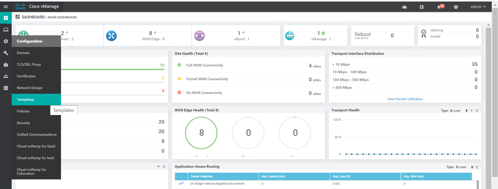
On the vManage GUI, navigate to Configuration => Templates
-
Click on the Feature tab and click on Add Template

-
Search for vedge in the search box and put a check mark next to vEdge Cloud. This will give the options to select Feature Templates applicable to the selected device type. Click on VPN to start configuring a VPN Template. This is going to be our VPN Template for VPN 0

-
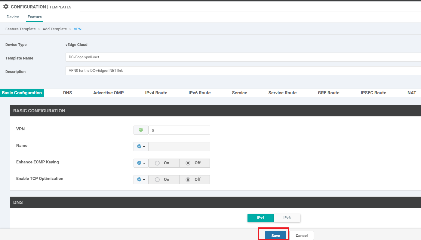
Give the Template a name of DCvEdge-vpn0 and a description of VPN0 for the DC-vEdges INET and MPLS link

-
Under Basic Configuration, specify the VPN as 0 (zero)

-
Populate the Primary and Secondary DNS Address as 10.y.1.5 and 10.y.1.6 respectively, where y is 1 if you’re on the SJC DC and 2 if you’re on the GHI DC (the email with lab details should enumerate which DC you’re on). Set the drop down to Global in order to enter the IPs. The option to enter the Secondary DNS server will pop up once the Primary is populated

-
Under IPv4 Route, click on New IPv4 Route and specify the Prefix as Global. Populate 0.0.0.0/0 as the prefix and click on Add Next Hop

-
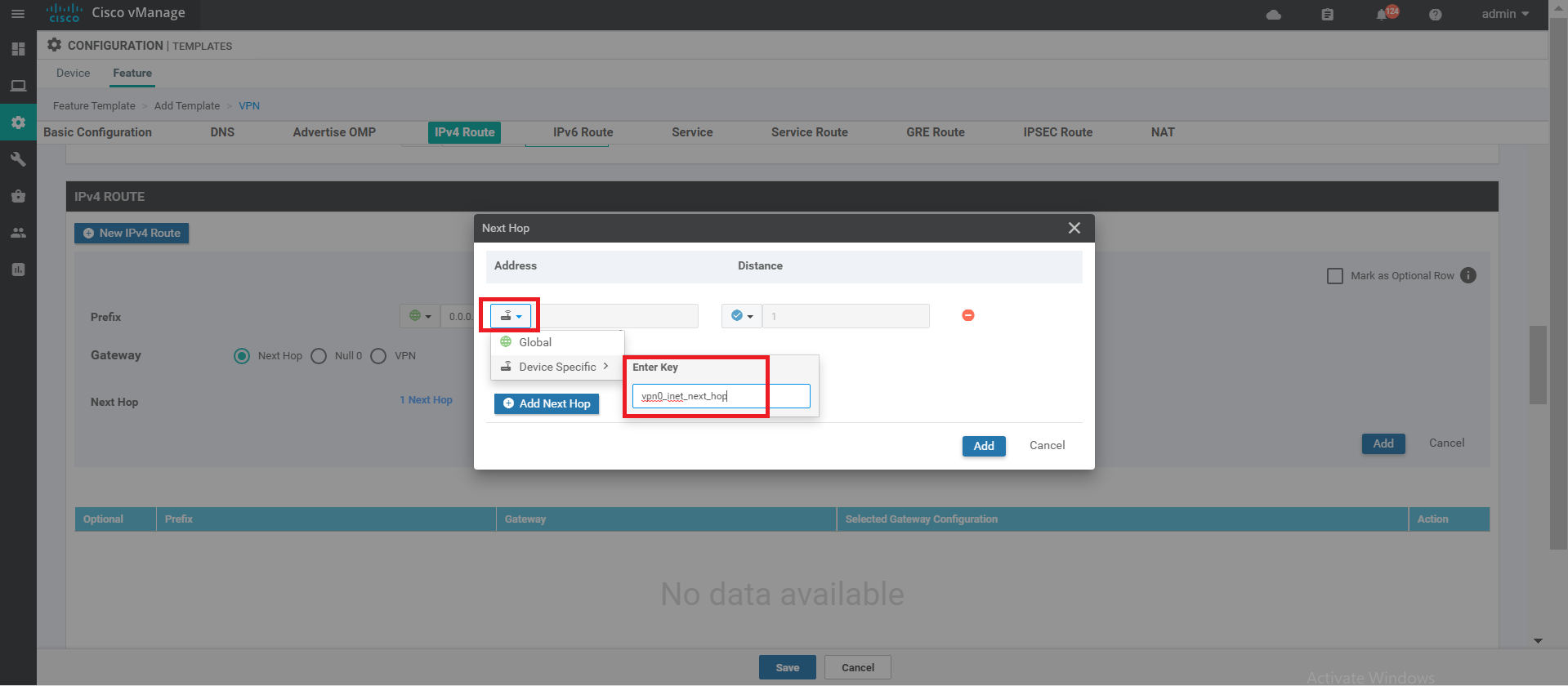
Click on Add Next Hop again in the popup window

-
From the drop down, set the value to Device Specific and enter the key as vpn0_inet_next_hop
-
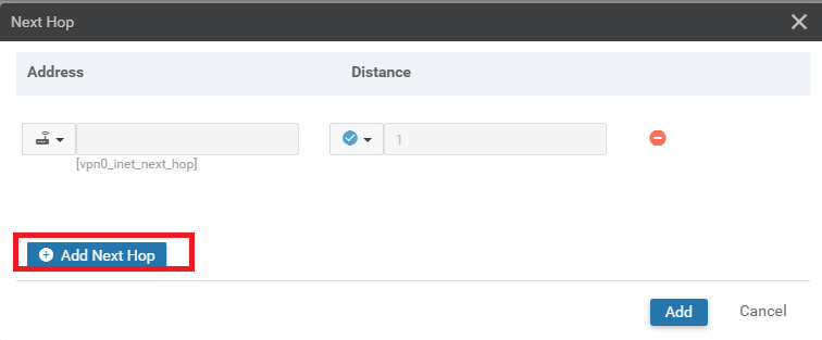
Click on Add Next Hop. We will now be adding the default route for the MPLS link
-
Choose Device Specific from the drop down and give it a name of vpn0_mpls_next_hop. Click on Add

-
Make sure the IPv4 Route screen shows 2 Next Hop and click on Add

-
Back at the main Feature Template page, click on Save. This will create our VPN 0 Feature Template
- Creating the DC-vEdge VPN Feature Templates
-
- Creating the VPN512 Feature Template
- Creating the INET VPN Interface Feature Template
- Creating the MPLS VPN Interface Feature Template
- Creating the Mgmt VPN Interface Feature Template
- Creating a Device Template and Attaching Devices
- Activity Verification
Creating the VPN512 Feature Template
We will make use of the just created VPN 0 Feature Template to create our VPN 512 Feature Template.
-
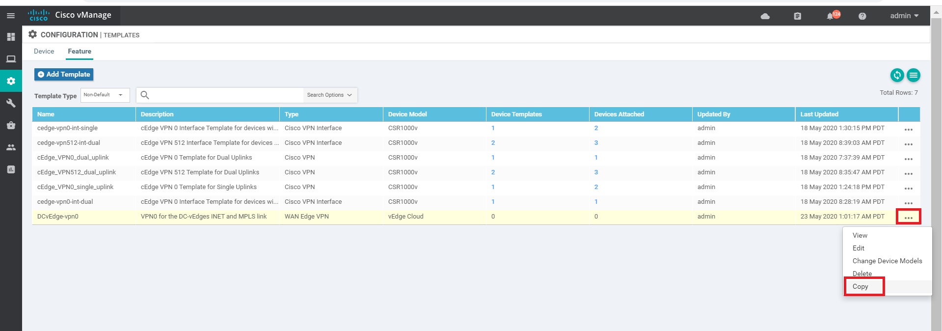
On the Configuration => Templates page navigate to the Feature tab and look for DCvEdge-vpn0. Click on the three dots for this template and click on Copy
-
Give the Template a name of DCvEdge-vpn512 and a description of VPN512 for the DC-vEdges. Click on Copy

-
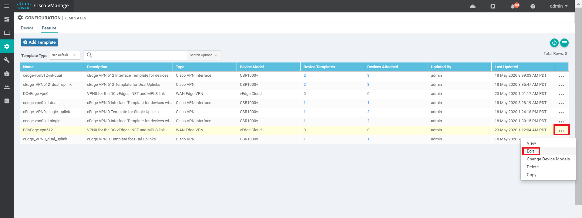
Click on the three dots for the newly created template and click on Edit
-
Update the Description, if it hasn’t been updated and change the VPN to 512

-
Scroll down to the IPv4 Route section and click on the pencil icon to edit the 0.0.0.0/0 Route

-
Click on 2 Next Hop. We will be removing the MPLS next hop entry and modifying the name of the INET next hop for the management network

-
Click on the minus sign to remove the MPLS next hop

-
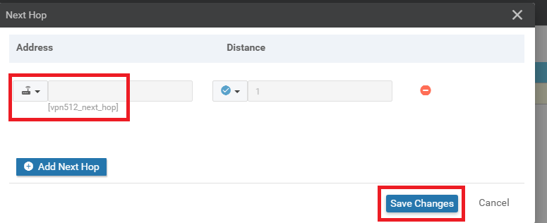
Update the Device Specific information for the first entry to vpn512_next_hop. Click on Save Changes
-
Click on Save Changes again. The Update IPv4 Route page should now reflect 1 Next Hop

-
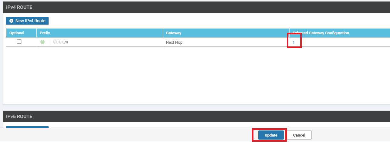
Click on Update on the main feature template page to save the changes that we have made. The Selected Gateway Configuration should have the number 1 against it
We have created our VPN512 Feature Template
- Creating the DC-vEdge VPN Feature Templates
-
-
- Creating the INET VPN Interface Feature Template
- Creating the MPLS VPN Interface Feature Template
- Creating the Mgmt VPN Interface Feature Template
- Creating a Device Template and Attaching Devices
- Activity Verification
Creating the INET VPN Interface Feature Template
We are now going to set up the VPN Interface Feature Templates for the Internet link. This template specifies the configuration for the interfaces in a VPN. There will be two interfaces in VPN 0 (INET and MPLS) and one interface in VPN 512. Let’s start off with configuring the INET interface.
-
From Configuration => Templates on the Feature tab, Add a new template. Search for ved in the search box and choose the vEdge Cloud Device. Click on VPN Interface Ethernet to start creating our VPN Interface Template

-
Populate the details on this page as given below. Screenshots can be used for reference. Click on Save once the fields have been populated
Section Field Global or Device Specific (drop down) Value Template Name NA DC-vEdge_INET Description NA INET interface for the DC-vEdges Basic Configuration Shutdown Global No Basic Configuration Interface Name Device Specific vpn0_inet_if_name Basic Configuration IPv4 Address Device Specific vpn0_inet_if_ip Tunnel Tunnel Interface Global On Tunnel Color Device Specific vpn0_inet_if_color Tunnel - Allow Service All Global On 


This completes the configuration of our INET Interface Feature Template. Notice that we will be populating quite a few details when the Device is attached to a Device Template which contains this Feature Template.
- Creating the DC-vEdge VPN Feature Templates
-
-
-
- Creating the MPLS VPN Interface Feature Template
- Creating the Mgmt VPN Interface Feature Template
- Creating a Device Template and Attaching Devices
- Activity Verification
Creating the MPLS VPN Interface Feature Template
We are now going to set up the VPN Interface Feature Template for the MPLS link, making a copy from the INET template that we created in the previous section.
-
Identify the DC-vEdge_INET Feature Template from Configuration => Templates => Feature tab. Click on the three dots in the extreme right-hand side of the template and click Copy. Name it DC-vEdge_MPLS with a Description of MPLS interface for the DC-vEdges. Click on Copy

-
Click on the 3 dots next to the copied template and choose to Edit. Modify the details as per the table given below and click on Update (we have changed the Device Specific names to reflect mpls and set the restrict to On)
Section Field Global or Device Specific (drop down) Value Template Name NA DC-vEdge_MPLS Description NA MPLS interface for the DC-vEdges Basic Configuration Shutdown Global No Basic Configuration Interface Name Device Specific vpn0_mpls_if_name Basic Configuration IPv4 Address Device Specific vpn0_mpls_if_ip Tunnel Tunnel Interface Global On Tunnel Color Device Specific vpn0_mpls_if_color Tunnel Restrict Global On 

This completes the configuration of the MPLS VPN Interface Feature Template.
- Creating the DC-vEdge VPN Feature Templates
-
-
-
-
- Creating the Mgmt VPN Interface Feature Template
- Creating a Device Template and Attaching Devices
- Activity Verification
Creating the Mgmt VPN Interface Feature Template
Just like before, we will make a copy of the DC-vEdge_INET Feature Template and use that for our VPN 512 Management Interface Template.
-
Locate the DC-vEdge_INET template created before, click on the 3 dots at the end and choose to Copy the template

-
Rename it to DC-vEdge_mgmt_int with a Description of MGMT interface for the DC-vEdges. Click on Copy

-
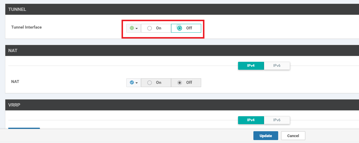
Click on the 3 dots next to the newly created template and choose to Edit. Populate the details in the template as per the following table and click on Update. The Tunnel Interface has been set to Off
Section Field Global or Device Specific (drop down) Value Template Name NA DC-vEdge_mgmt_int Description NA MGMT interface for the DC-vEdges Basic Configuration Shutdown Global No Basic Configuration Interface Name Device Specific vpn512_mgmt_if_name Basic Configuration IPv4 Address Device Specific vpn512_mgmt_if_ip Tunnel Tunnel Interface Global Off 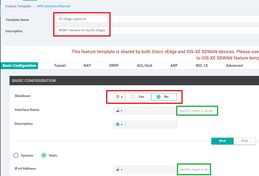
We have creatd the VPN 512 Interface Template.
-
-
-
-
-
-
- Creating a Device Template and Attaching Devices
- Activity Verification
Creating a Device Template and Attaching Devices
Most of the work has already been done, with respect to creating the building blocks for our Device Templates. All that’s left is ensuring we create a Device Template with the corresponding Feature Templates and associate the Devices with the Template.
-
Navigate to the Configuration => Templates section and make sure you’re on the Device tab. Click on Create Template => From Feature Template

-
Choose Device Model as vEdge Cloud, and give the Template a name of DCvEdge_dev_temp. Give it a Description of Device template for the DC-vEdges

-
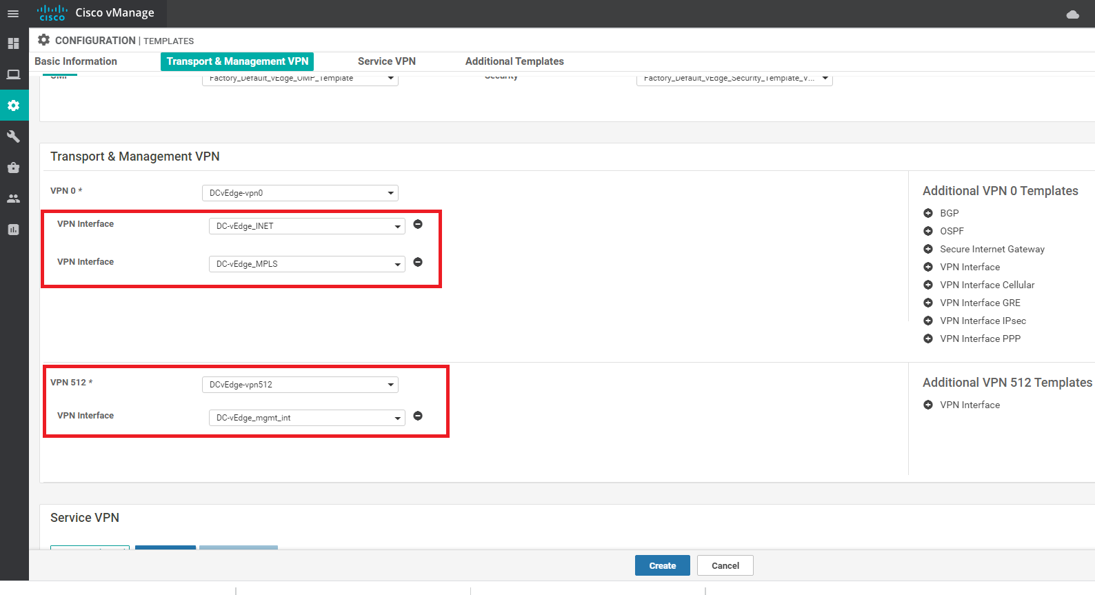
Under Transport and Management choose the VPN 0 template as DCvEdge-vpn0 and the VPN 512 Template as DCvEdge-vpn512. Click twice on VPN Interface under Additional VPN 0 Templates. This will add two VPN Interfaces where we can associate our VPN Interface Templates. Click once on VPN Interface under Additional VPN 512 Templates to add a VPN Interface for VPN 512

-
Populate the VPN Interface fields from the drop down as show below and click on Create
-
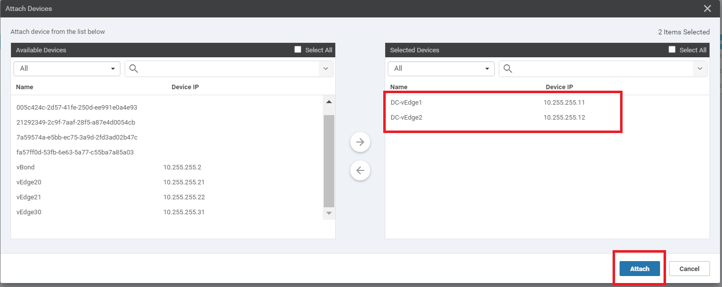
Click on the three dots next to the newly created Device Template named DCvEdge_dev_temp and click on Attach Devices

-
Move DC-vEdge1 and DC-vEdge2 to the list of selected devices and click on Attach
-
Click on the three dots next to DC-vEdge1 and choose Edit Device Template. Enter the details as shown below (these are the Device Specific paramters we had defined in the Feature Templates, along with some parameters that are part of the Default Templates pre-populated in the Device Template). Click on Update once everything has been populated exactly as shown below. This information can also be picked up from the table given in the topology section

-
Click on the three dots next to DC-vEdge2 and choose Edit Device Template. Enter the details as shown below. Click on Update once done

Click on Next to proceed
-
At this point, you can simply click on Configure Devices to start pushing the configuration to the devices, or you can click on an individual device on the left-hand side and followed by Config Diff and then Side by Side to view a comparison of the current configuration on the device vs. what will be pushed out. This is great for reviewing the configuration that is going to be pushed and for learning the syntax. Note that we are adding the MPLS interface and relevant configuration on our devices, which wasn’t done before.


-
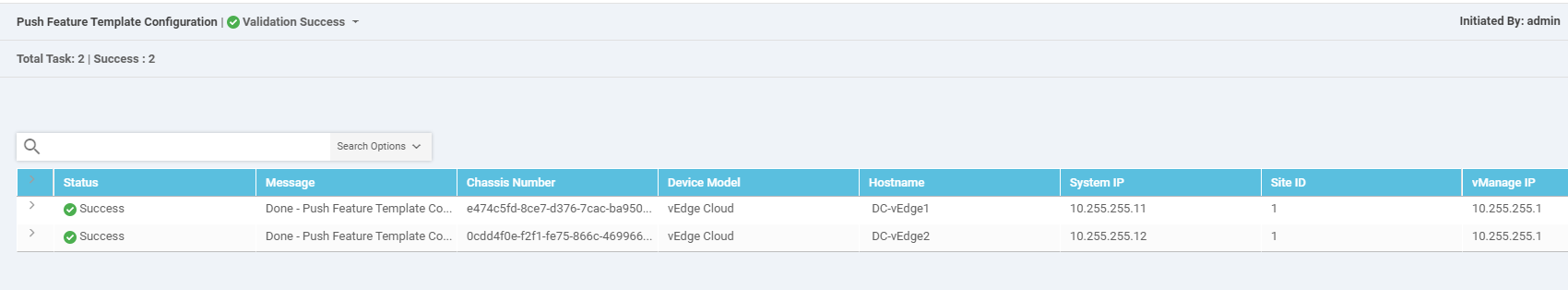
On clicking on Configure Devices, you will need to put a check mark next to Confirm configuration changes on 2 devices and click on OK

-
Once complete, you should see a Success message against each device that was configured
 Tip: In case a loss of connectivity occurs as a result of the configuration changes that were pushed to the Devices, there is an automatic rollback timer of 6 minutes which kicks in. Devices will revert to their previous configuration in this case. The rollback timer can be configured (on the final page before we choose to configure our devices, there is a hyperlink in the bottom left hand corner)
-
-
-
-
-
-
-
- Activity Verification
Activity Verification
-
Go to Configuration => Devices and you should see that the two DC-vEdges are now in vManage mode

-
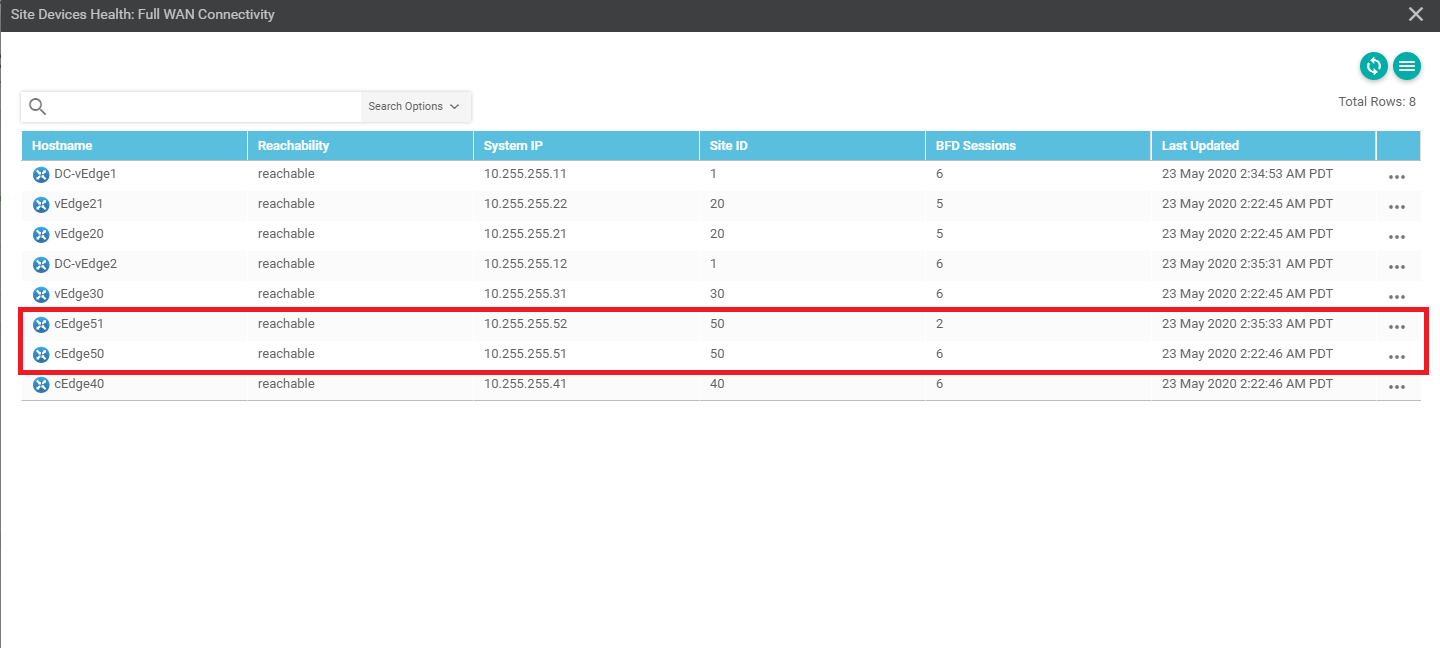
On checking the main dashboard (Dashboard => Main Dashboard) we should see 5 sites with full WAN connectivity (if you recall, we previously could see only 4 sites with full WAN connectivity and Site 50 wasn’t showing up at all. This was because BFD sessions weren’t established on the MPLS link)

-
If we click on Full WAN Connectivity, Site 50 now shows up
-
Use Putty to access cEdge51 and issue
show bfd sessions. We now see BFD sessions with DC-vEdge1 and DC-vEdge2, on the MPLS link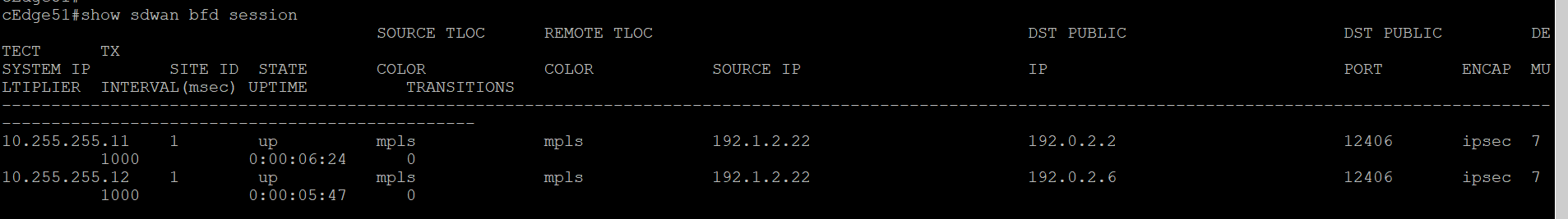
This completes the verification activity
-
-
-
-
-
-
-
-