- Verifying the current lab setup
- Creating the cEdge40 VM
- Onboarding cEdge40
- Initial Configuration - non SD-WAN mode
- Setting up Feature Templates
- Creating and Attaching Device Templates
- Copying the Bootstrap file and converting to SD-WAN IOS-XE mode
- Onboarding Verification
Verifying the existing lab setup
The vManage, vBond and vSmarts have been deployed along with Sites 1, 20 and 30. We will start by verifying the existing setup.
-
Log in to vManage by clicking on the bookmark or navigating to https://192.168.0.6. Use the following credentials:
Username Password admin admin 
-
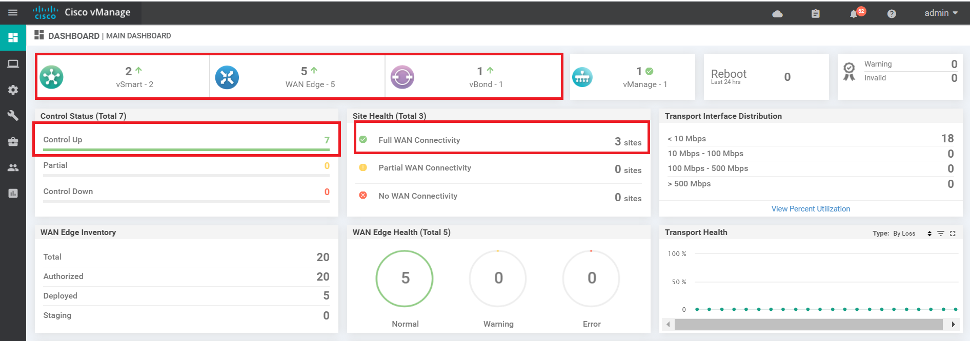
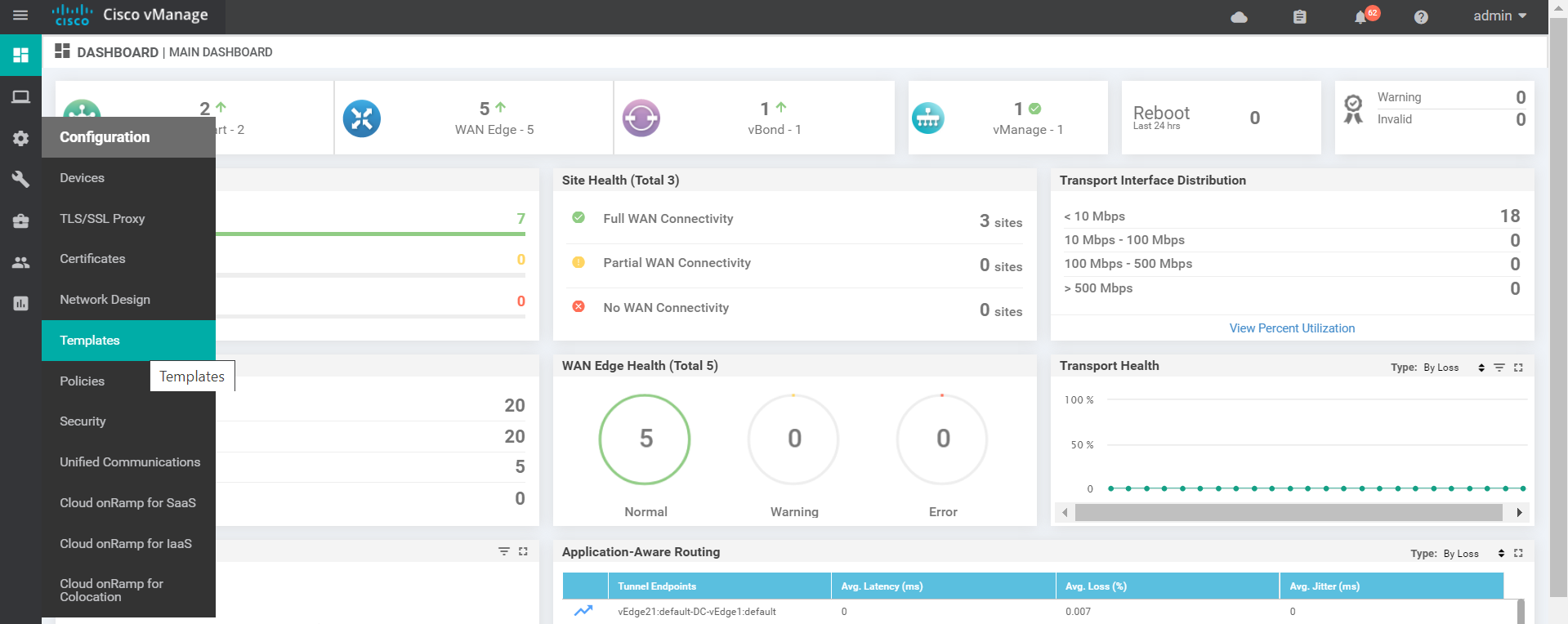
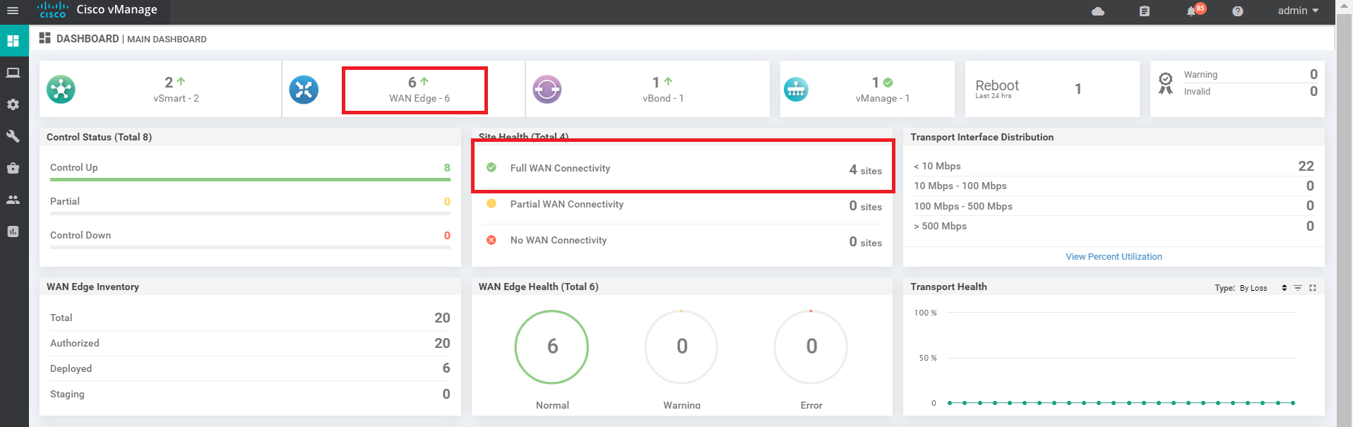
On logging in, you should see 2 vSmarts, 1 vBond and 1 vManage along with 5 WAN Edges. 7 control planes should be up and 3 sites should have WAN connectivity. If you see 7 WAN Edges with 9 Control Planes, that is OK as well (since it depends on the scenario chosen while registering for the lab)
-
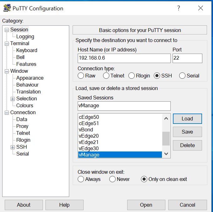
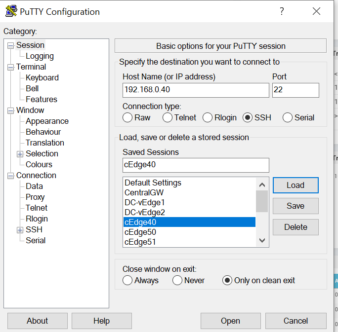
Open and log in to the vManage via the CLI - fire up Putty and double click the saved session for vManage or SSH to 192.168.0.6. Use the same credentials as the GUI.
-
Issue
show control connectionsand you should see the vManage talking to the vSmarts, vBond and vEdges. Note the System IP and the fact that all the connections are up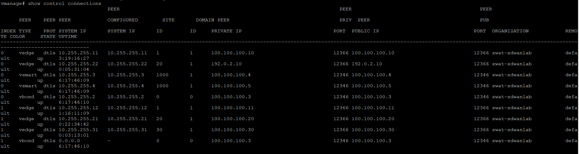
Look at the System IP to see which device has the vManage established a control connection with. There should be 5 (or 7, depending on the selected lab scenario) connections to vEdges. This completes the verification activity.
-
- Creating the cEdge40 VM
- Onboarding cEdge40
- Initial Configuration - non SD-WAN mode
- Setting up Feature Templates
- Creating and Attaching Device Templates
- Copying the Bootstrap file and converting to SD-WAN IOS-XE mode
- Onboarding Verification
Creating the cEdge40 VM
Overview
We will be deploying a cEdge in Site 40 via vCenter. Make note of the following information for this section. The IP Addressing will not be used for some of the Network Adapters until later.
| SITE ID | SYSTEM ID | VM | Network Adapter | Network | Interface | IP | Gateway |
|---|---|---|---|---|---|---|---|
| 40 | 10.255.255.41 | cEdge40-podX | Network Adapter 1 | Management | GigabitEthernet1 | 192.168.0.40/24 | 192.168.0.1 |
| Network Adapter 2 | Internet | GigabitEthernet2 | 100.100.100.40 | 100.100.100.1 | |||
| Network Adapter 3 | MPLS40 | GigabitEthernet3 | 192.1.2.18/30 | 192.1.2.17 | |||
| Network Adapter 4 | Site40-VPN10 | GigabitEthernet4 | 10.40.10.2/24 | ||||
| Network Adapter 5 | Site40-VPN20 | GigabitEthernet5 | 10.40.20.2/24 | ||||
| Network Adapter 6 | Site40-VPN30 | GigabitEthernet6 | 10.40.30.2/24 |
Deploying the VM on vCenter
-
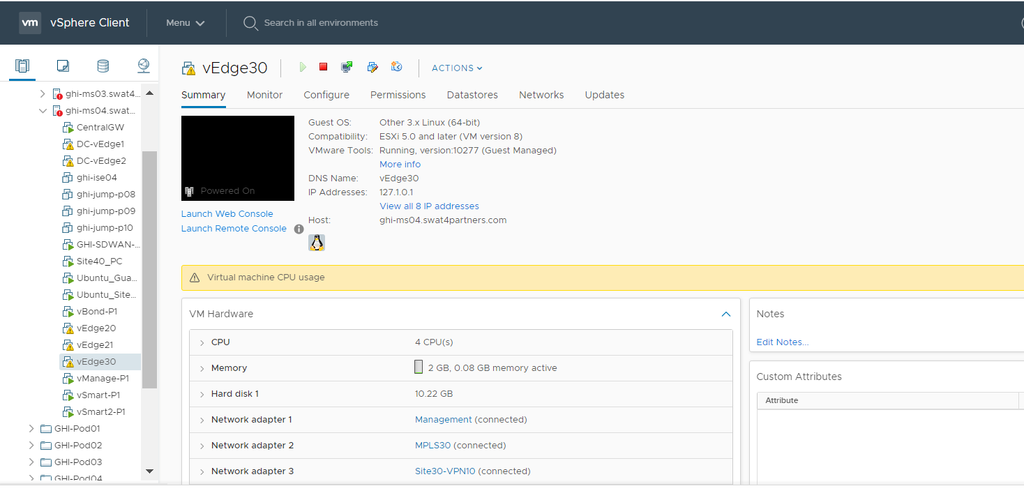
Click on the bookmark for vCenter or navigate to the following URL: https://10.2.1.50/ui if connected to the GHI DC and 10.1.1.50/ui if connected to the SJC DC. Log in with the credentials provided for your POD.
-
We should see the vEdges from previous sections of the lab deployed.
-
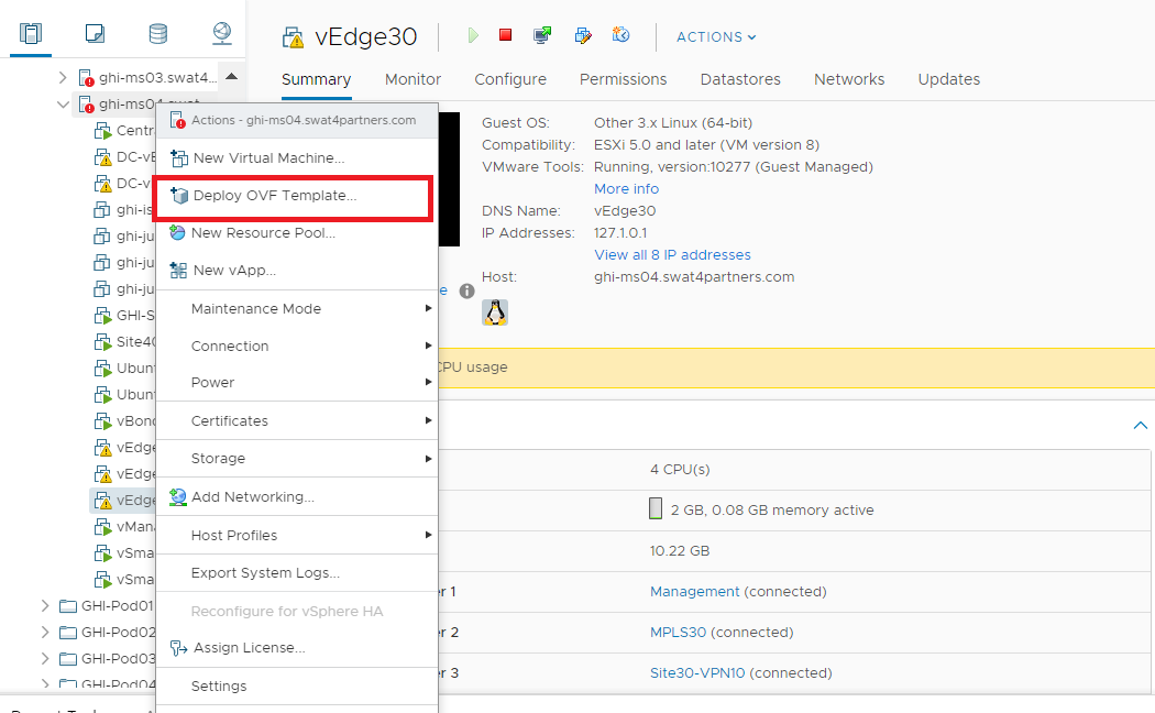
Right click on the host and choose to Deploy OVF Template
-
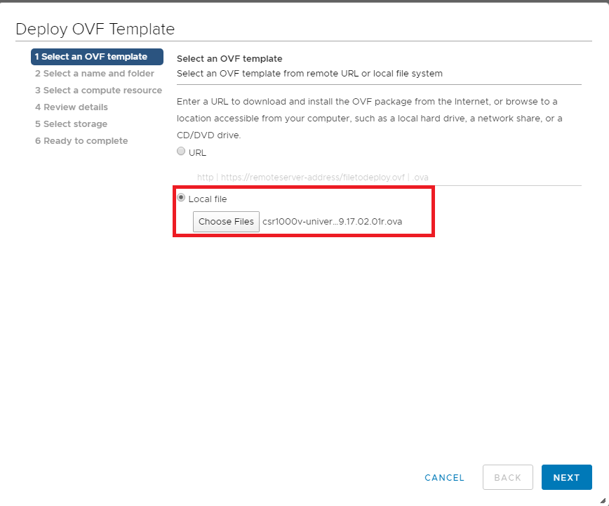
Choose the Local file option and click on Choose files. Navigate to the SD-WAN images folder and select the file beginning with csr1000v-univer. Click on Next.
-
Change the Virtual Machine name to cEdge40-podX and click on Next (X is your POD number, image below doesn’t reflect the podX suffix)
Note: We will only use the podX suffix over here to distinguish between different VMs in our Data Center. The rest of the guide will refer to this VM as cEdge40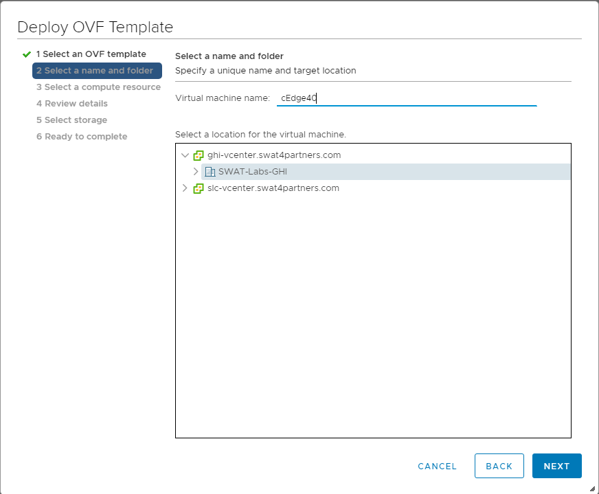
-
Select the host assigned to you (image shown as an example only) and click on Next
Note: If the screen gets stuck over here at Validating then close Chrome and open the vCenter in Internet Explorer, going through the same steps. Deployment should go through. This is a known issue with Google Chrome.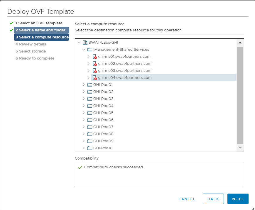
-
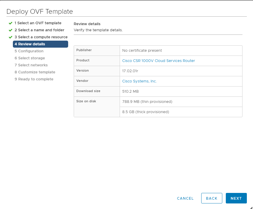
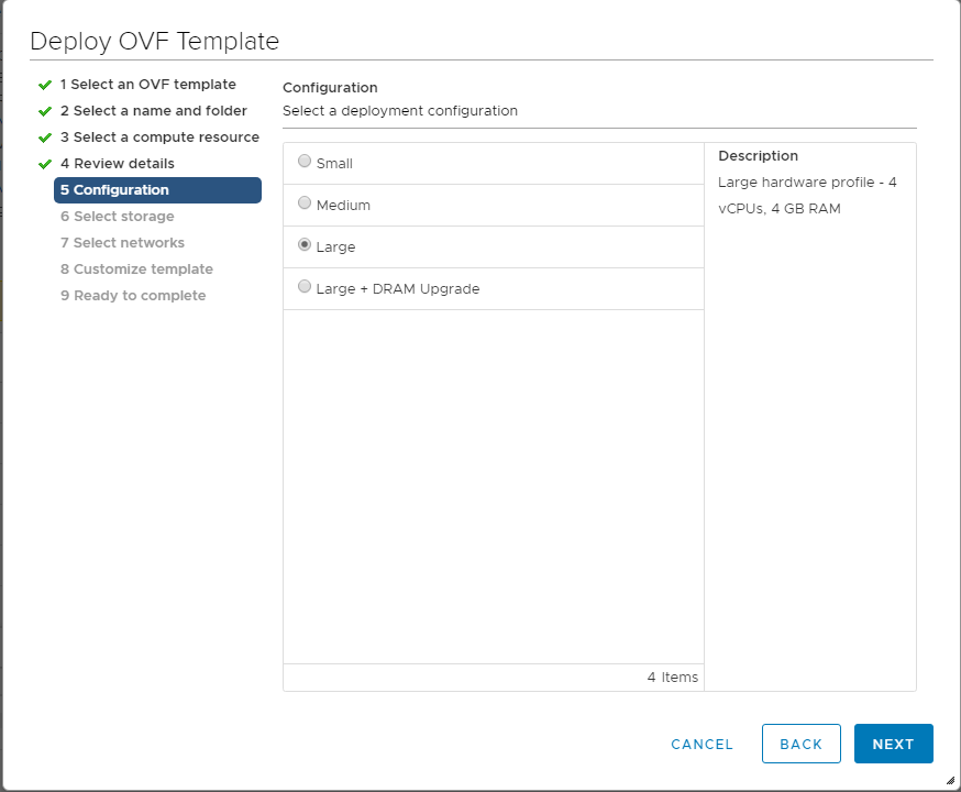
Review the details shown and click on Next. Select the Large option (4 vCPUs and 4 GB RAM) and click on Next
-
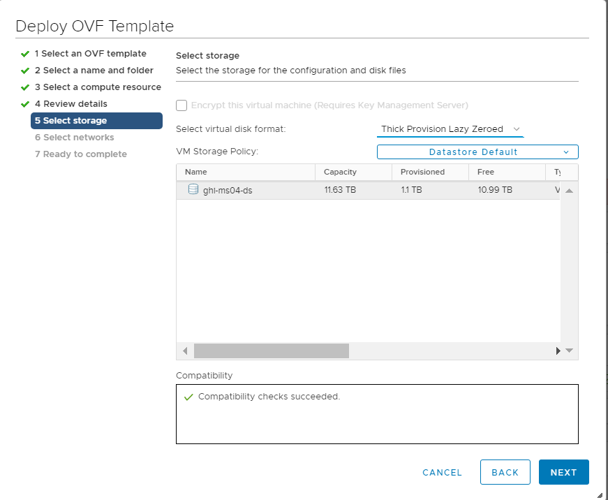
Choose the Datastore and click on Next.
-
Populate the VM Networks as per the image given below
Important: Please make sure that these look exactly as shown below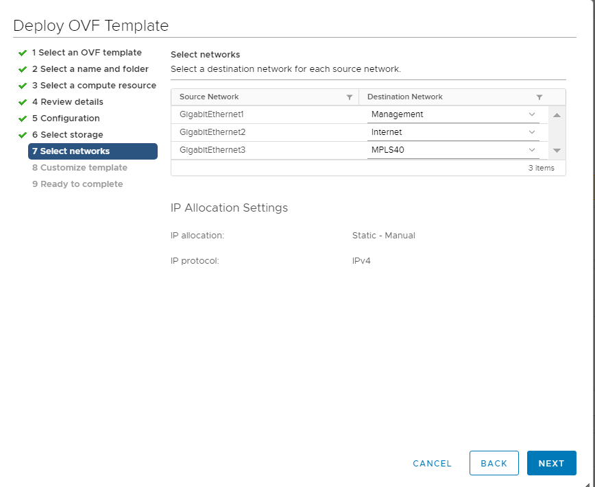
-
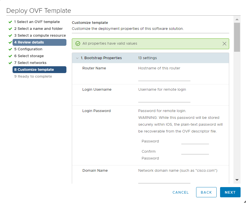
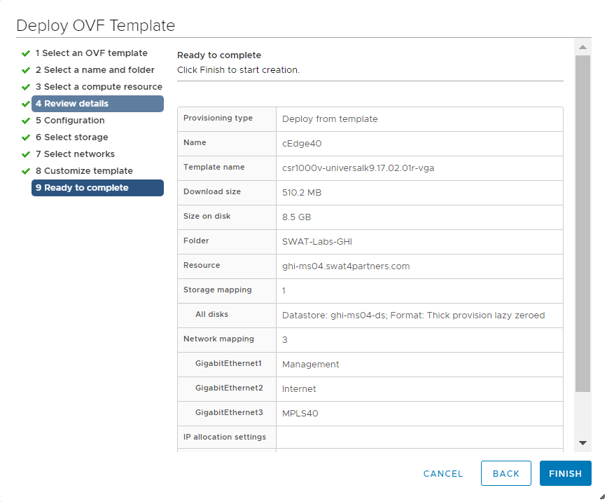
Click Next on Customize Template and then Click on Finish to deploy your cEdge40 VM. Please do not power on the VM at this point
-
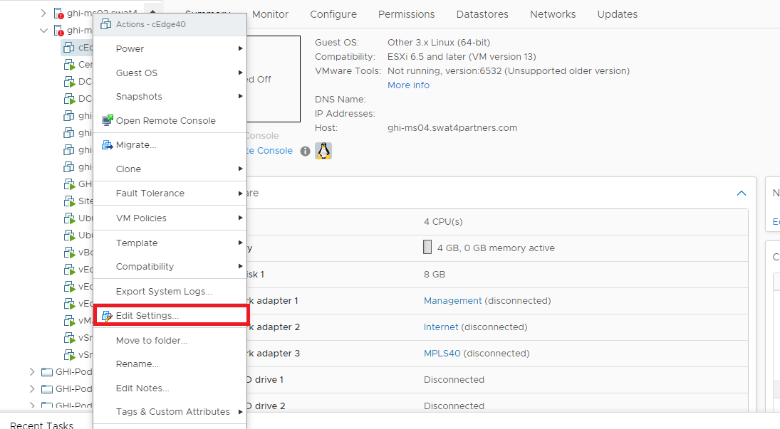
Once the VM is deployed, right click cEdge40-podX and click Edit settings.
-
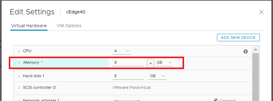
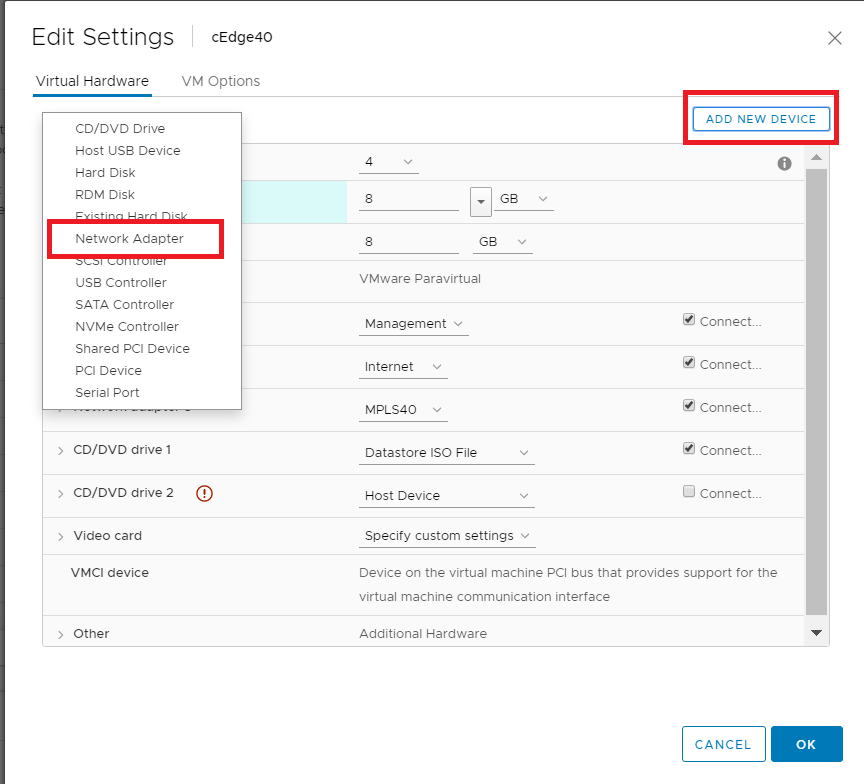
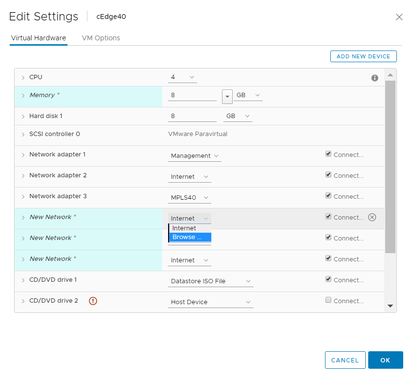
Change the memory to 8 GB (needed since we will be deploying an IPS module on this cEdge, which requires a minimum of 8 GB RAM) and choose to Add a new device (top right corner). Select Network Adapter to add one (since our deployed VM has only 3 Network Adapters but we will need 6 for our lab). Do this twice more for a grand total of 6 Network Adapters
-
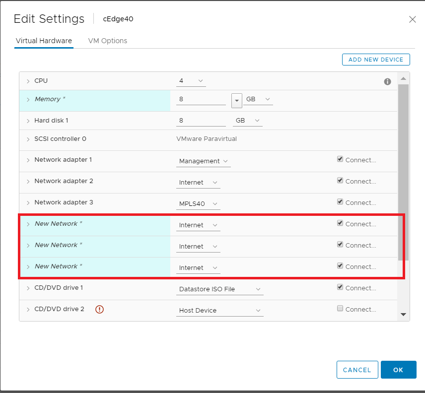
Click on the drop down next to the first New Network and click on Browse
-
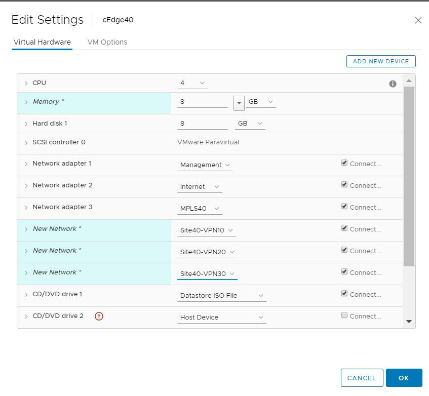
Choose the Site40-VPN10 Network and click on OK. Do the same for the next two network adapters, allocating them to Site40-VPN20 and Site40-VPN30 respectively. Make sure the Network Adapters match with the second image below and click on OK again
Warning: The Network Adapter mapping might vary based on the version of cEdge being deployed. Sometimes, trial and error is the easiest way to figure out which Network Adapter maps to which interface on the cEdge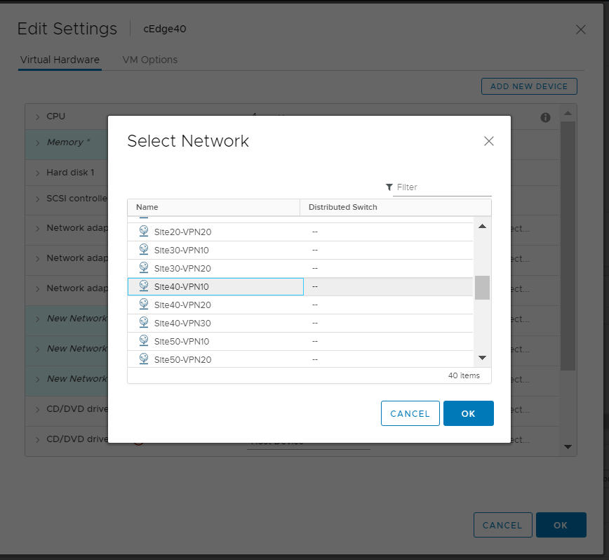
-
Click on cEdge40-podX and choose to power it on
-
-
- Onboarding cEdge40
- Initial Configuration - non SD-WAN mode
- Setting up Feature Templates
- Creating and Attaching Device Templates
- Copying the Bootstrap file and converting to SD-WAN IOS-XE mode
- Onboarding Verification
Onboarding cEdge40
Initial Configuration - non SD-WAN mode
Use the following information in this section (some of the information will be used later)
| SITE ID | SYSTEM ID | VM | Network Adapter | Network | Interface | IP | Gateway |
|---|---|---|---|---|---|---|---|
| 40 | 10.255.255.41 | cEdge40 | Network Adapter 1 | Management | GigabitEthernet1 | 192.168.0.40/24 | 192.168.0.1 |
| Network Adapter 2 | Internet | GigabitEthernet2 | 100.100.100.40 | 100.100.100.1 | |||
| Network Adapter 3 | MPLS40 | GigabitEthernet3 | 192.1.2.18/30 | 192.1.2.17 | |||
| Network Adapter 4 | Site40-VPN10 | GigabitEthernet4 | 10.40.10.2/24 | ||||
| Network Adapter 5 | Site40-VPN20 | GigabitEthernet5 | 10.40.20.2/24 | ||||
| Network Adapter 6 | Site40-VPN30 | GigabitEthernet6 | 10.40.30.2/24 |
-
We will first console in to the cEdge and set up an IP Address with basic routing to ensure that the cEdge can reach vManage and the Jumphost. This is done by issuing
ip route 0.0.0.0 0.0.0.0 192.168.0.1followed byinterface GigabitEthernet1and giving an IP Address to the interface throughip address 192.168.0.40 255.255.255.0. Make sure youno shutthe interface.Additionally, we will be SCP’ing files over to the cEdge (root certificates) from vManage
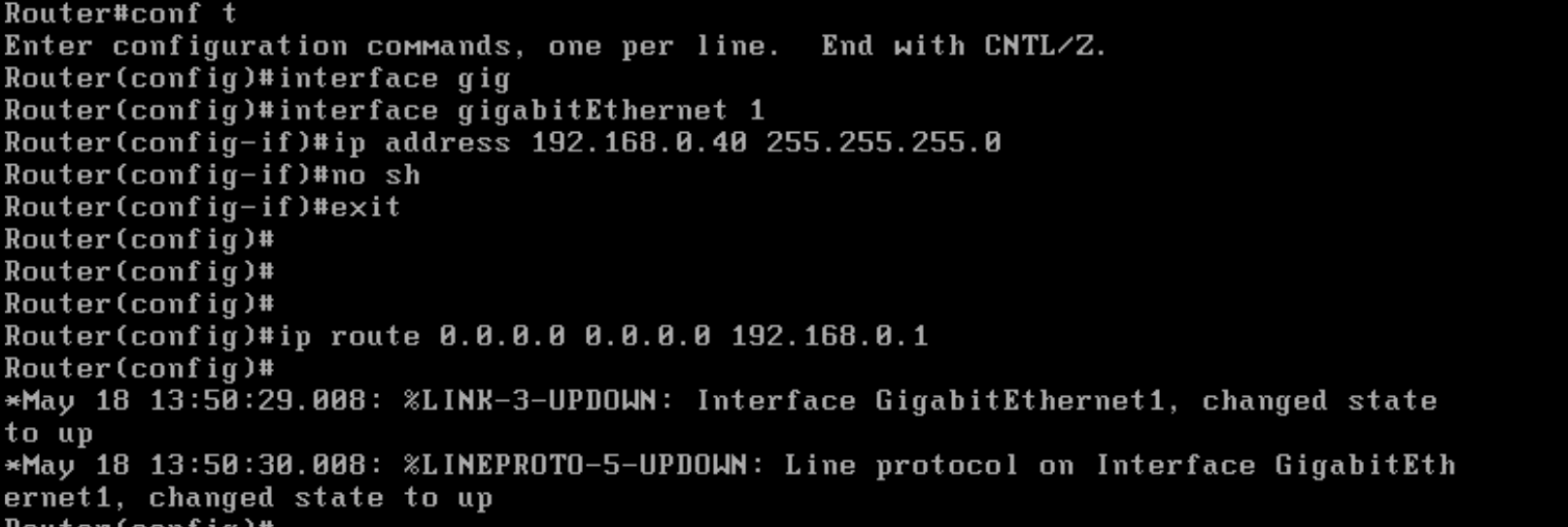
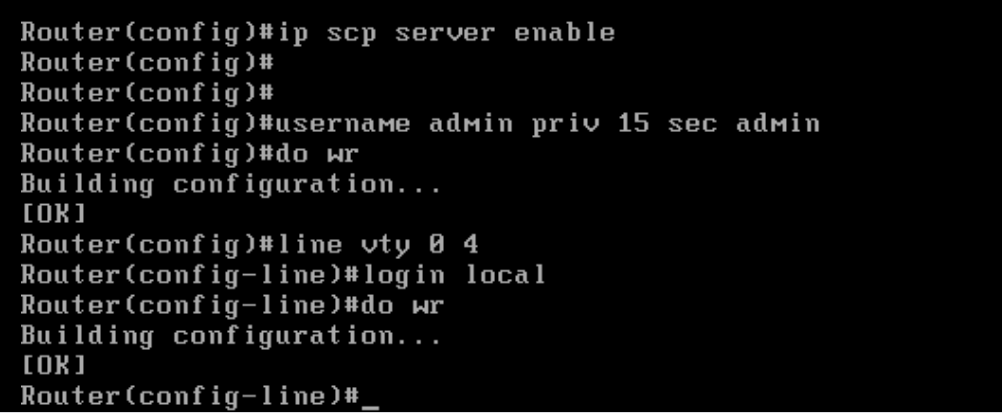
enable conf t interface GigabitEthernet1 ip address 192.168.0.40 255.255.255.0 no shut exit ip route 0.0.0.0 0.0.0.0 192.168.0.1 ip scp server enable username admin priv 15 sec admin line vty 0 4 login local do wr -
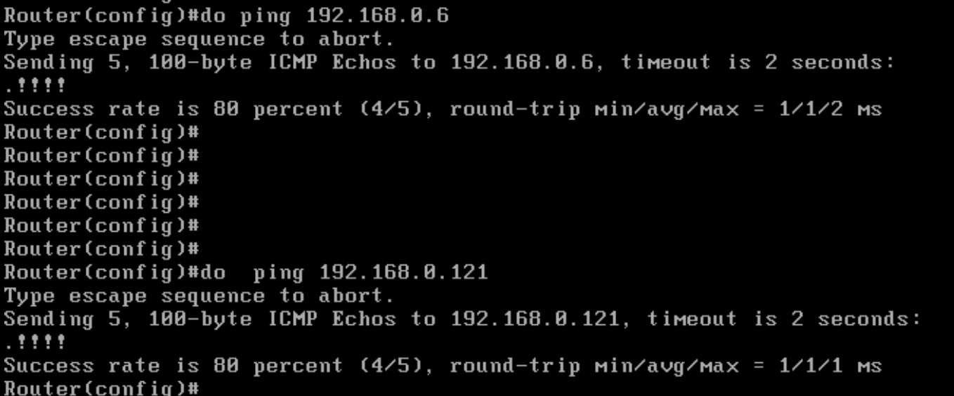
Verify connectivity to the vManage and the JumpHost (IP of the Jumphost might vary) by pinging 192.168.0.6 and/or the IP Address of your Jumphost
-
-
- Onboarding cEdge40
-
- Setting up Feature Templates
- Creating and Attaching Device Templates
- Copying the Bootstrap file and converting to SD-WAN IOS-XE mode
- Onboarding Verification
Setting up Feature Templates
Templates are the key configuration components of the Cisco SD-WAN solution. They help with deploying large scale solutions with minimal effort. While there is quite a lot of initial configuration that goes into setting up these templates, their usefulness is highlighted when we’re looking at onboarding multiple devices in a quick and efficient manner, reusing generic templates for devices.
Click here to access the SD-WAN Design Guide which has a section on Configuration Templates.
-
On the vManage GUI, navigate to Configuration (the cog wheel icon on the left) => Templates
-
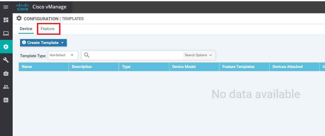
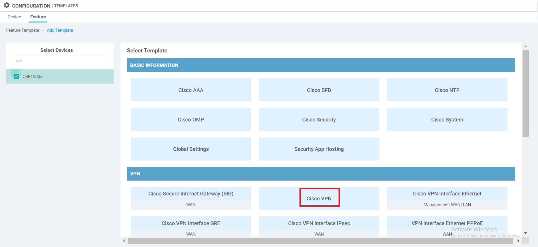
Click on the Feature tab to access the Feature templates. Click on Add Template
-
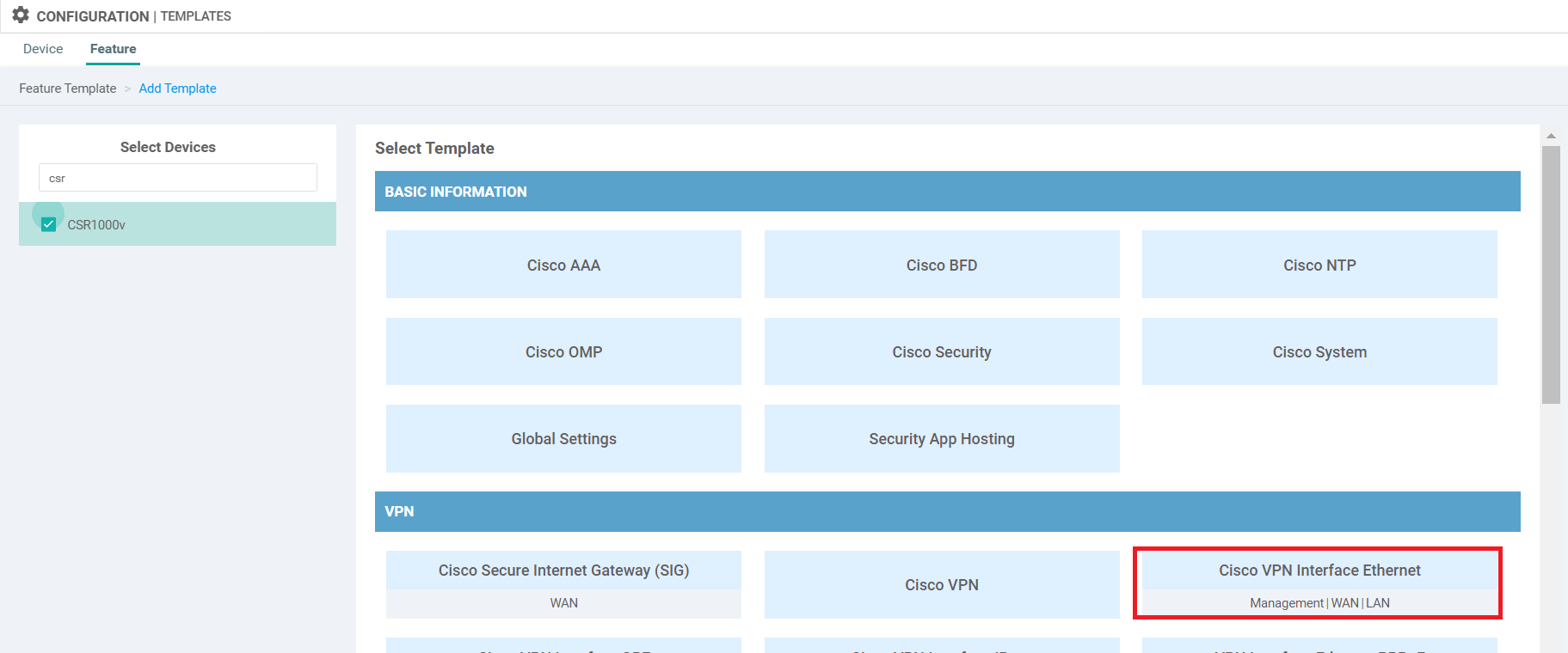
Search for csr and select CSR1000v on the left-hand side. This should give the option to select a template from the right. Choose Cisco VPN template
-
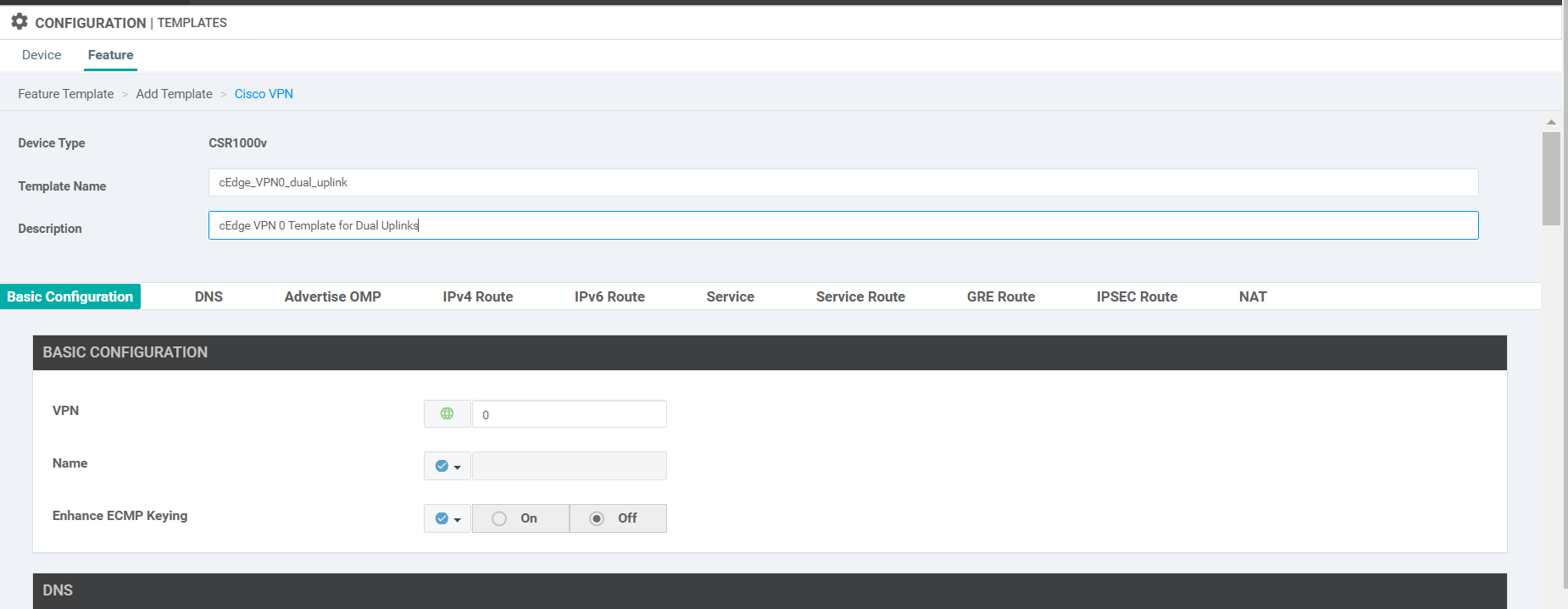
Name your template cEdge_VPN0_dual_uplink and give a description of cEdge VPN 0 Template for Dual Uplinks. Enter the VPN as 0.
-
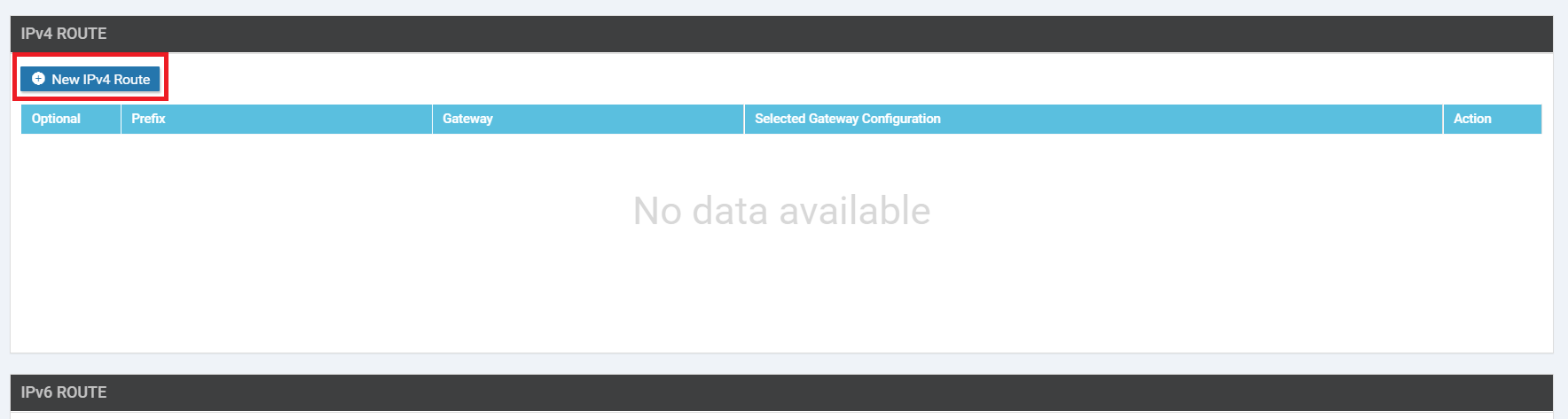
Click on IPv4 Route and then choose New IPv4 Route
-
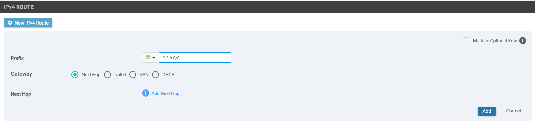
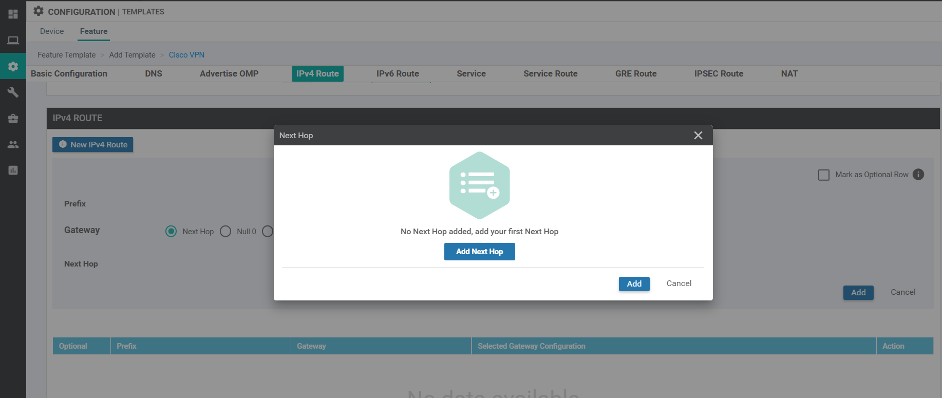
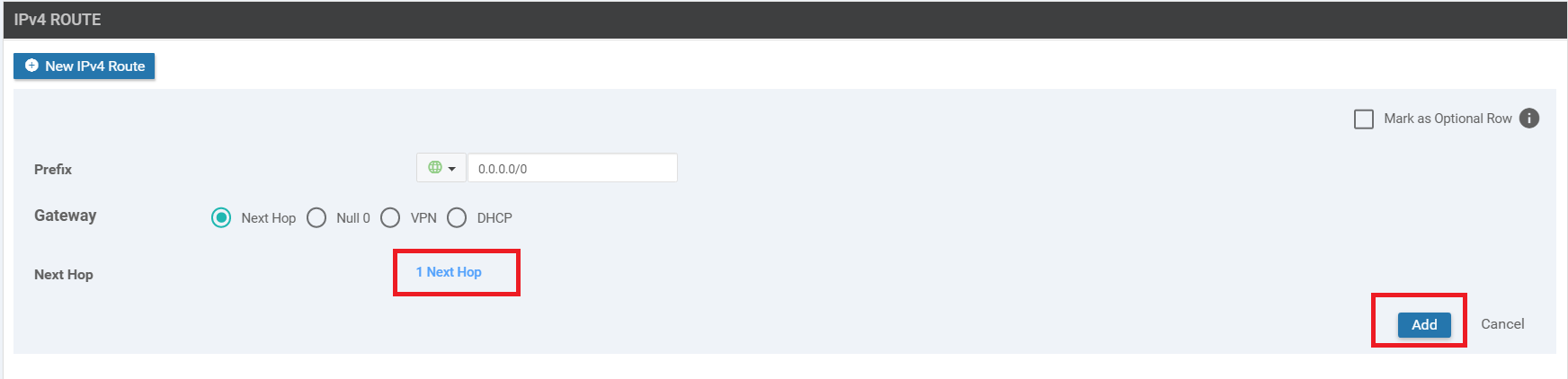
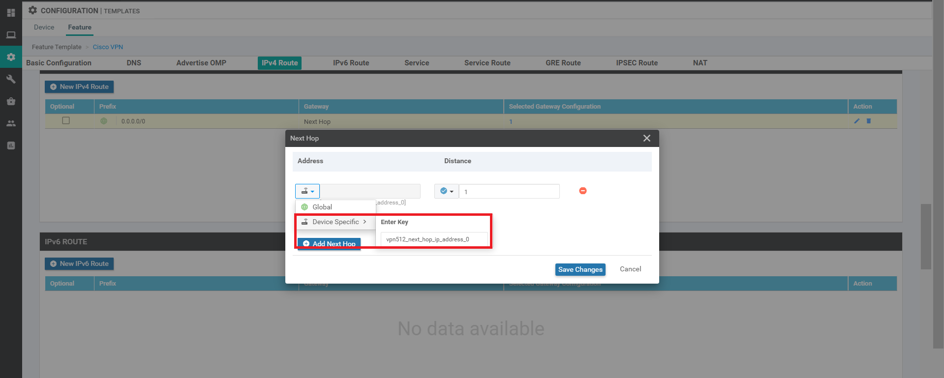
Enter the Prefix as 0.0.0.0/0 and click on Add Next Hop. We’re adding the default route for VPN 0 (draw parallels with the manual configuration that was done on the vEdges)
-
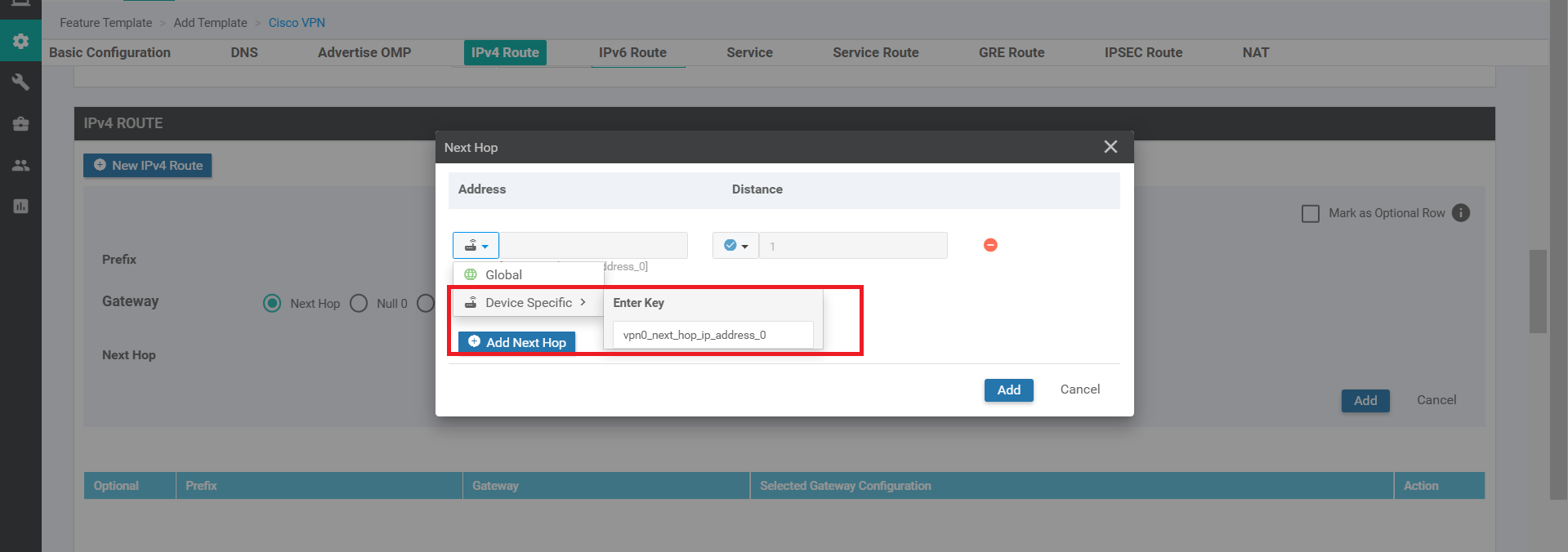
Click on Add Next Hop again and choose Device Specific from the Address drop down. Enter vpn0_next_hop_ip_address_0. Click on Add.
-
Make sure you have 1 Next Hop showing up in the IPv4 Route window and click on Add again. Once on the main Template page, click on Save to create your Feature Template
-
Choose to Add Template, searching and selecting CSR1000v like before. This time, choose to add a Cisco VPN Interface Ethernet template
-
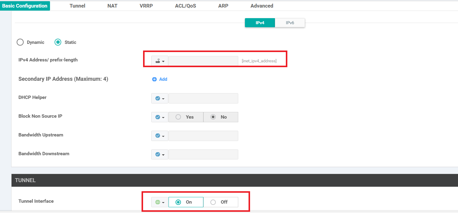
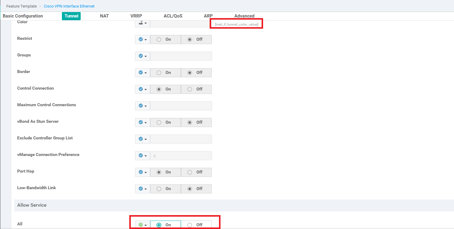
Populate the details as shown in the table below. Screenshots may be used as reference. Click on Save at the end to create your Feature Template.
Section Field Global or Device Specific (drop down) Value Template Name NA cedge-vpn0-int-dual Description NA cEdge VPN 0 Interface Template for Devices with a dual uplink Basic Configuration Shutdown Global No Basic Configuration Interface Name Global GigabitEthernet2 Basic Configuration - IPv4 IPv4 Address / prefix-length Device Specific inet_ipv4_address Tunnel Tunnel Interface Global On Tunnel Color Device Specific inet_if_tunnel_color_value Tunnel - Allow Service All Global On 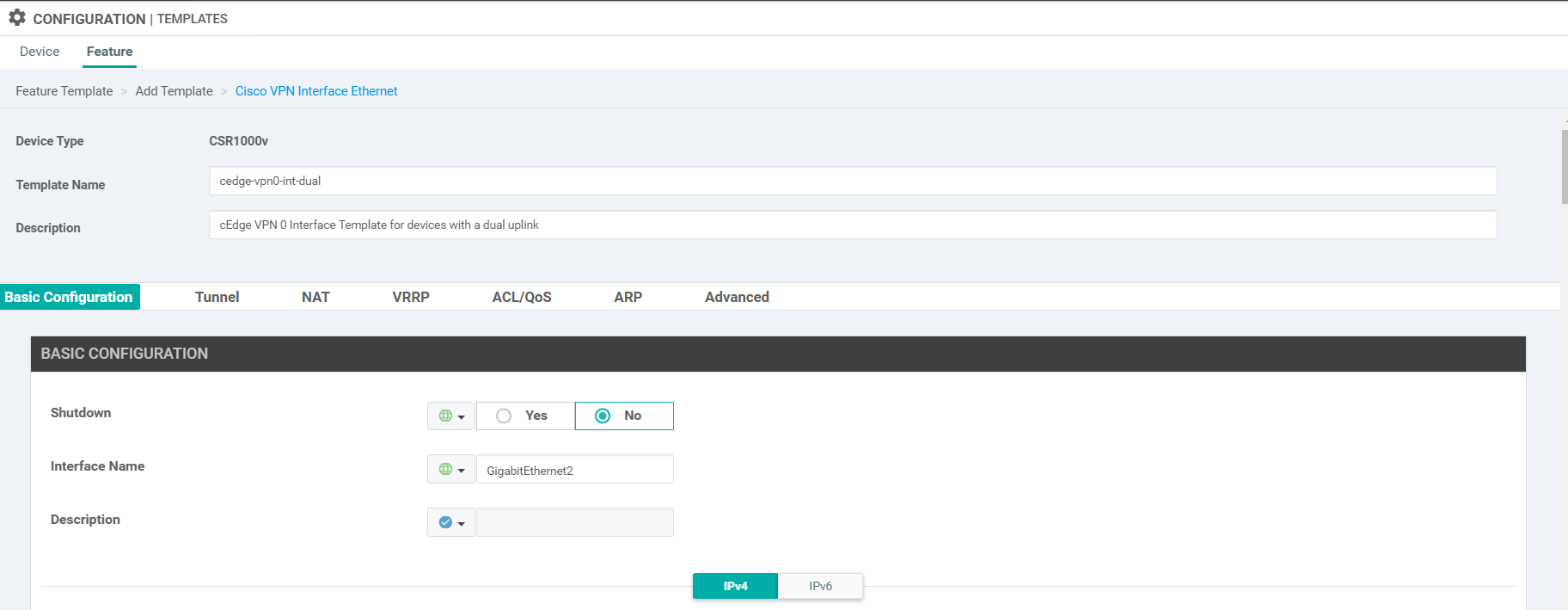
-
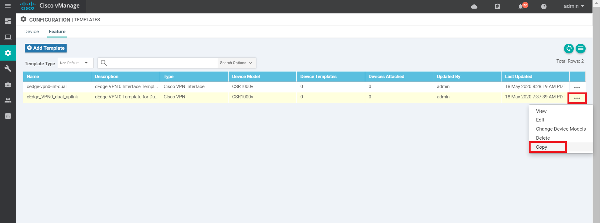
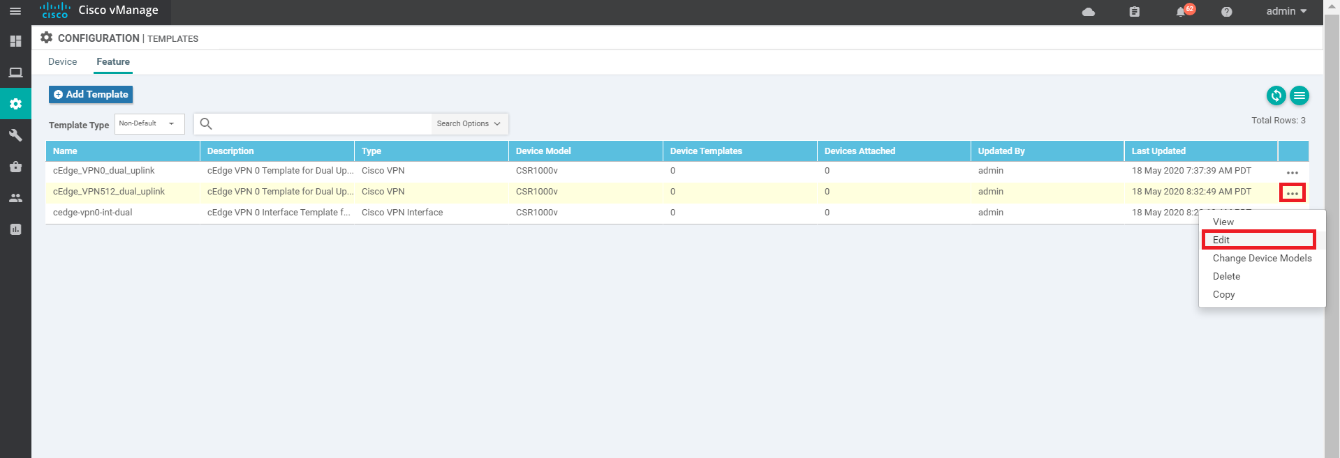
You should now see the feature template created. We now need to create the feature templates for VPN 512 and the VPN 512 Interface. The power of templates becomes apparent at this point since we can copy a template that was created previously and tweak it as per the requirement. Click on the three dots at the end of the cEdge_VPN0_dual_uplink template and click on Copy
-
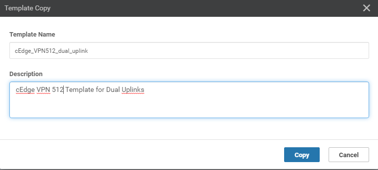
You will be prompted to name the copied template. Give it a name of cEdge_VPN512_dual_uplink and update the description to cEdge VPN 512 Template for Dual Uplinks (sometimes, the description doesn’t get updated and needs to be done again when editing the template. Reference bug ID CSCvu19244, which is fixed in vManage version 20.1.12). Click on Copy.
-
Click on the three dots next to the newly created template and choose to Edit. Notice that the description did not get updated in the screenshot below, so we will edit it while tweaking the template
-
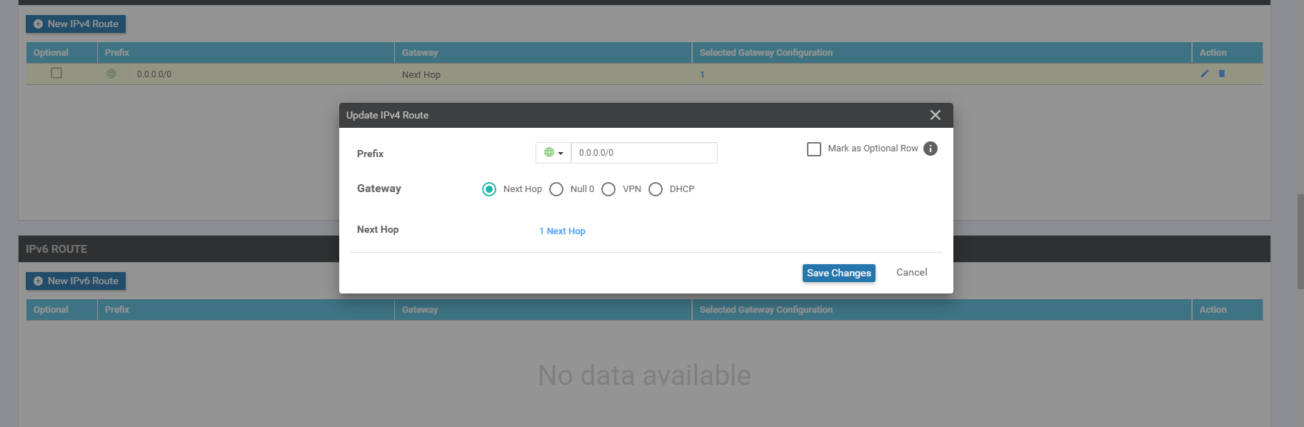
Populate the details as follows. To populate the IPv4 Route, click on the edit (pencil icon) next to the existing IPv4 Route and then click on 1 Next Hop. Edit and click on Update Changes
Section Field Global or Device Specific (drop down) Value Template Name NA cEdge_VPN512_dual_uplink Description NA cEdge VPN 512 Template for Dual Uplinks Basic Configuration VPN Global 512 IPv4 Route Update IPv4 Route - Next Hop Device Specific vpn512_next_hop_ip_address_0 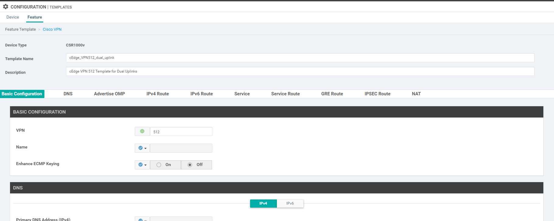
-
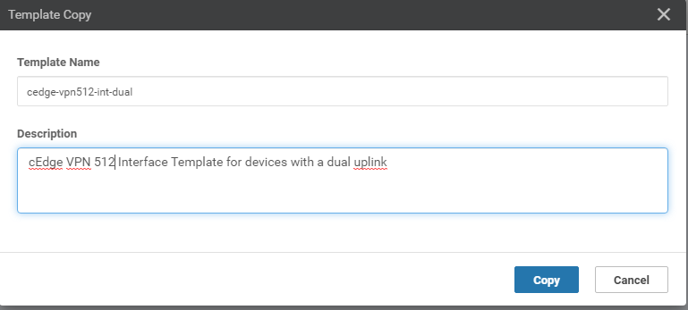
Make a copy of the VPN 0 Interface template so as to use it for VPN 512. Click on the 3 dots next to the template cedge-vpn0-int-dual and click on Copy. Update the name and description to cedge-vpn512-int-dual and cEdge VPN 512 Interface Template for devices with a dual uplink and click on Copy
-
Click on the three dots next to the newly copied template and choose to Edit it. Populate the details as given in the table below and click on Update Changes
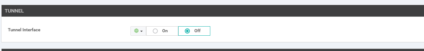
Section Field Global or Device Specific (drop down) Value Template Name NA cedge-vpn512-int-dual Description NA cEdge VPN 512 Interface Template for devices with a dual uplink Basic Configuration Shutdown Global No Basic Configuration Interface Name Global GigabitEthernet1 Basic Configuration - IPv4 IPv4 Address / prefix-length Device Specific vpn512_mgmt_ipv4_address Tunnel Tunnel Interface Global Off 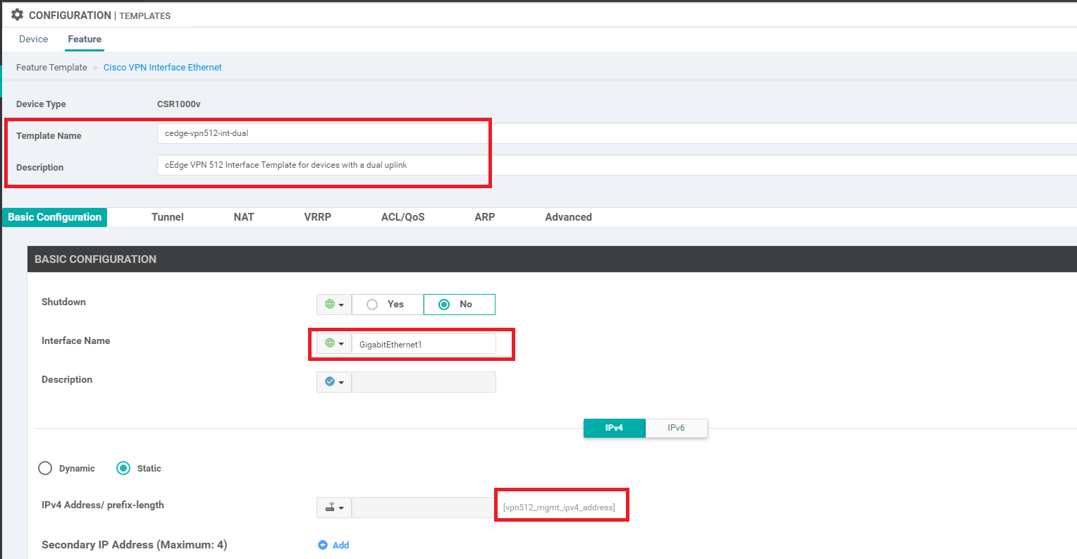
We are done with creating feature templates (for now) and while it was a lot of work, these templates can be reused and/or repurposed as required.
-
-
- Onboarding cEdge40
-
-
- Creating and Attaching Device Templates
- Copying the Bootstrap file and converting to SD-WAN IOS-XE mode
- Onboarding Verification
Creating and Attaching Device Templates
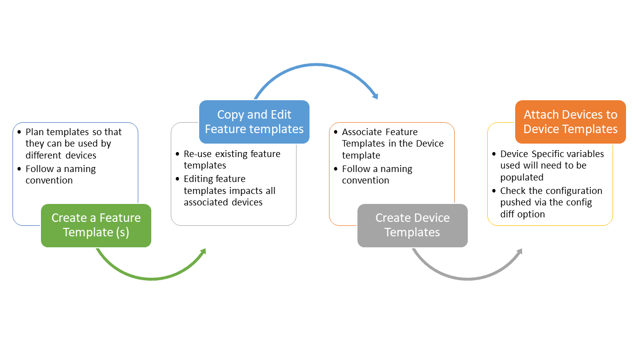
The feature templates created in the previous sections are referenced in Device Templates. Devices are then attached to Device Templates which pushes configuration to them, in line with the settings in the Feature templates. The general workflow for templates is given below
-
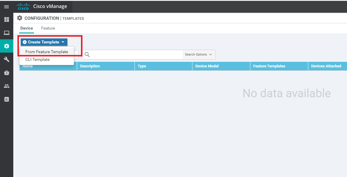
From the Configuration => Templates window, make sure you’re on the Device tab and click on Create Template. Choose to create a template From Feature Template
-
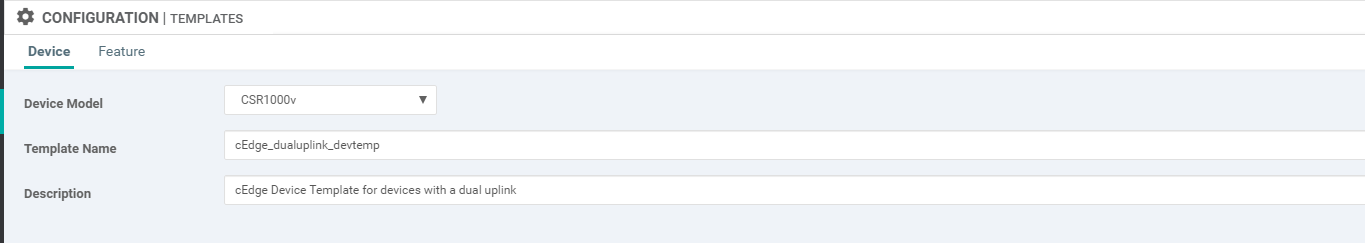
Choose CSR1000v as the Device Model and enter cedge_dualuplink_devtemp for the Template Name and cedge Device Template for devices with a dual uplink as the Description
-
In the template, navigate to the Transport & Management VPN section. Update the fields as per the table below, selecting templates which we created before and click on Create to create the Device Template
Tip: You can create templates on the fly if the template hasn’t already been created. This can be done via the Create Template hyperlink from the drop down menuImportant: To get the option of selecting a Cisco VPN Interface Ethernet as shown below, click on Cisco VPN Interface Ethernet on the right hand side under the Additional Templates portion of the screen. This applies to both the VPN 0 and the VPN 512 sectionsSection Field Sub Field Value (Drop Down) Transport and Management VPN Cisco VPN 0 cEdge_VPN0_dual_uplink Transport and Management VPN Cisco VPN 0 Cisco VPN Interface Ethernet cedge-vpn0-int-dual Transport and Management VPN Cisco VPN 512 cEdge_VPN512_dual_uplink Transport and Management VPN Cisco VPN 512 Cisco VPN Interface Ethernet cedge-vpn512-int-dual 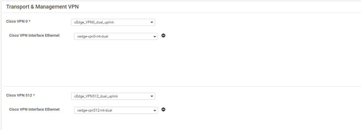
-
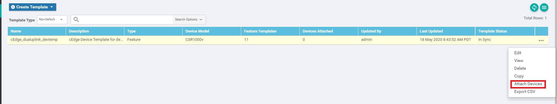
Once created, the Device Template will need to be attached to a Device for it to take effect. Click on the three dots (right-hand side) and click on Attach Devices
-
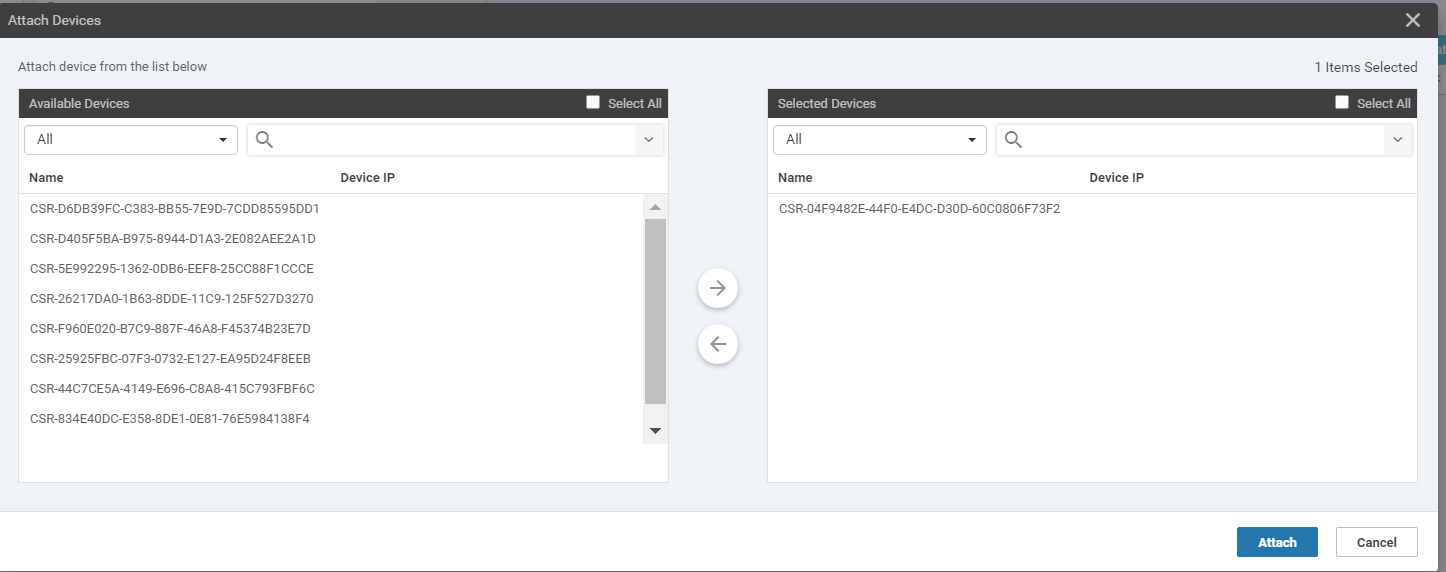
We will be presented with a list of devices that can be associated with this template. Choose any device, making note of the Name (e.g. the device with a name ending in 73F2 has been selected over here). Click on Attach
-
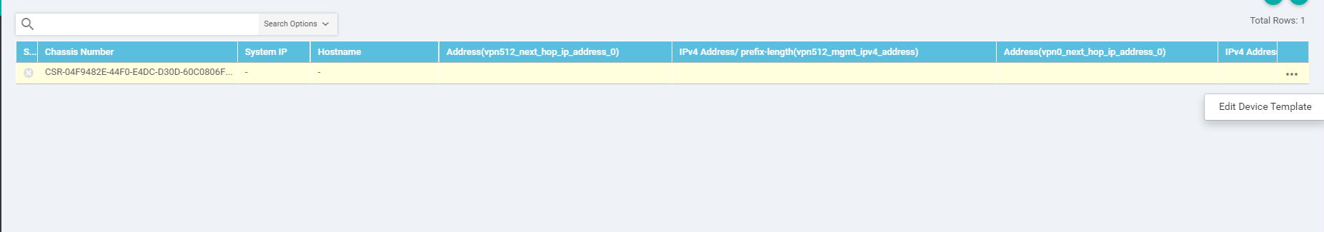
This should take you to a page which shows the attached device. Click on the three dots (right-hand side) and click on Edit Device Template. Also, make note of the cross mark next to the device name, on the left-hand side. This is the point where we need to enter details for the device specific values populated in the Feature Templates.
-
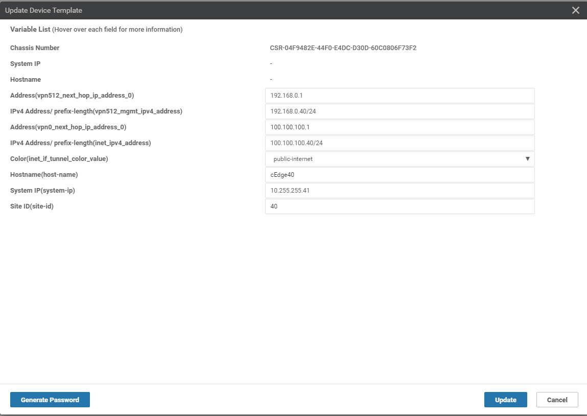
Enter details as per the screenshot below (these can be found in the table referenced at the beginning of this page) and click on Update. Once the fields have been populated, the cross mark should change to a green check mark.
-
Click on the entry in the Device List to view the configuration that will be pushed to the device. Notice that the vBond IP and the Organization Name have been populated. These are taken from the vManage Administration => Settings page, where they need to be populated. Click on Configure to configure the device.
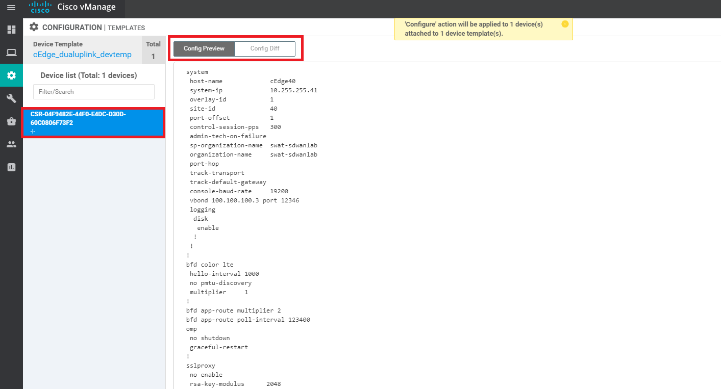
Since this isn’t a device that exists (as of now), the configuration push is scheduled for later, when a device is associated with this Device Name (the one ending in 73F2). This is done in the next section
-
-
- Onboarding cEdge40
-
-
-
- Copying the Bootstrap file and converting to SD-WAN IOS-XE mode
- Onboarding Verification
Copying the Bootstrap file and converting to SD-WAN IOS-XE mode
We will be generating a Bootstrap file and placing it in the flash of the device we want to bring up. The device (cEdge40) should come up and establish control connections with vManage, along with establishing BFD sessions with other devices.
-
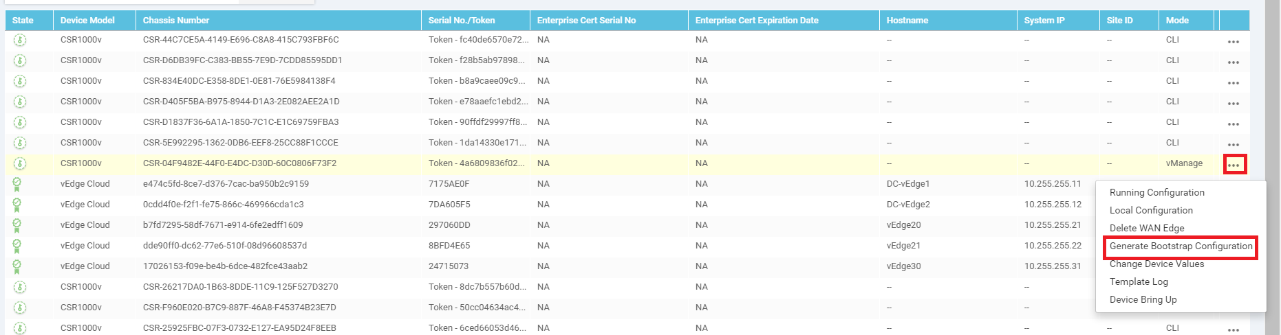
Go to Configuration => Devices
-
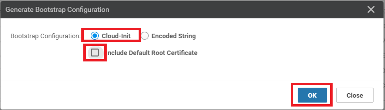
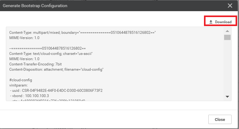
Identify the Chassis Number that was selected before, while attaching a Device to the Template. In this case, it ended in 73F2. Click on the three dots on the right-hand side and click on Generate Bootstrap Configuration. Choose Cloud-Init and uncheck Include Default Root Certificate. Click on OK
-
Download the bootstrap file (will get saved to the Downloads folder by default). It should be a file beginning with CSR…
-
Rename this to ciscosdwan_cloud_init.cfg. Note that the name should match exactly as is enumerated here, else Bootstrapping will not work. If a file already exits with the same name, choose to overwrite.
 Tip: On bootup, a cEdge looks for a file on it’s USB port (if a bootable USB drive is connected) and in bootflash:. The file name must match as above for Cloud type devices (i.e. CSR1K). For physical devices, the file name should be ciscosdwan.cfg. If the file is present on the USB drive and in bootflash:, the one in bootflash: takes precedence
 -
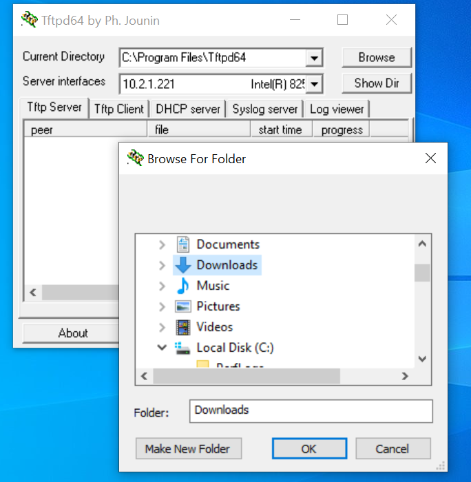
From the Jumphost Desktop, start TFTPD64. Click on Browse and choose the Downloads folder (or wherever the renamed .cfg file has been stored)
-
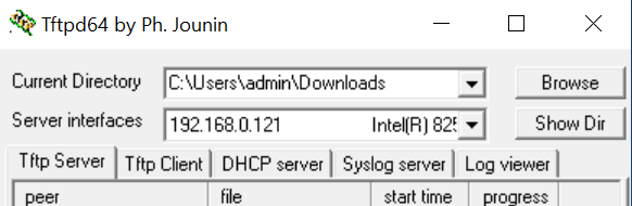
Choose the 192.168.0.X IP from the Server Interfaces drop down
-
Log in to the CLI of cEdge40 (we can log in via Putty now, using the saved session or by SSH’ing to 192.168.0.40) and issue
copy tftp: bootflash:. Specify a Remote Host IP of your Jumphost (192.168.0.121 in this case). The source and destination file name should be ciscosdwan_cloud_init.cfg. The file should get copied over to bootflash: successfully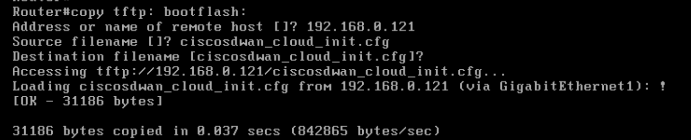
copy tftp: bootflash: -
Log in to the CLI of the vManage (again, via the saved Putty session or by SSH’ing to 192.168.0.6) and issue the following commands to SCP the ROOTCA.pem file over to cEdge40
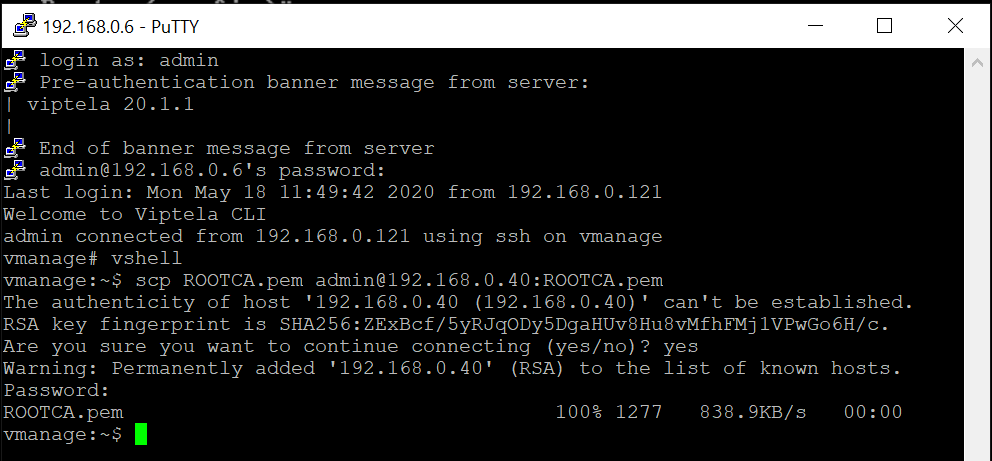
 vshell
 scp ROOTCA.pem admin@192.168.0.40:ROOTCA.pem
 yes
 admin
The last admin over there is the password of cEdge40
-
Go back to the CLI of cEdge40 and issue
controller-mode enablefrom privilege mode. Confirm and this should lead to the device rebooting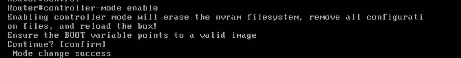
controller-mode enable
We have completed this section of the lab and will now need to wait for the cEdge to reboot. On rebooting, it should pick up the configuration file from bootflash: and connect to the vManage/vSmarts/other vEdges. This will be verified in the next section.
-
-
-
-
-
-
-
- Onboarding Verification
Onboarding Verification
-
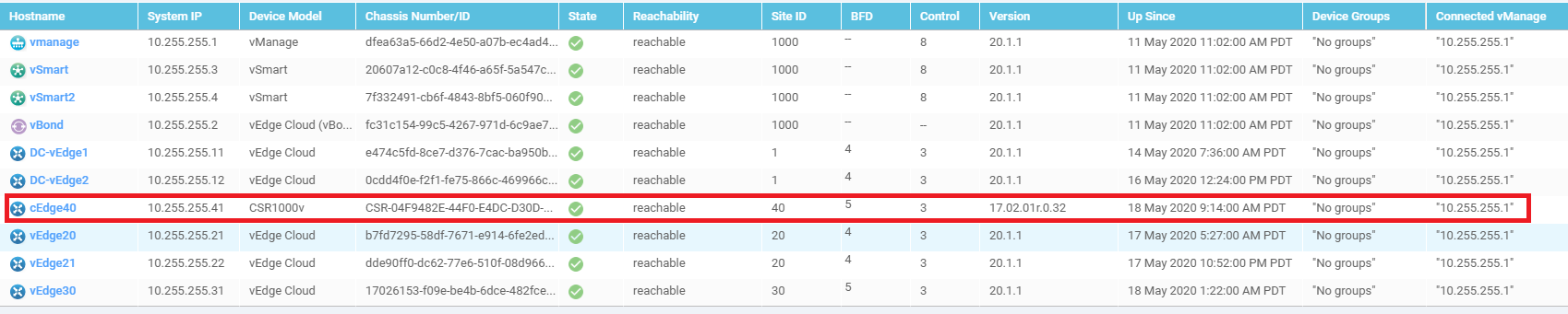
On the vManage GUI, go to Monitor => Network. You should see the cEdge40 successfully added on vManage.
-
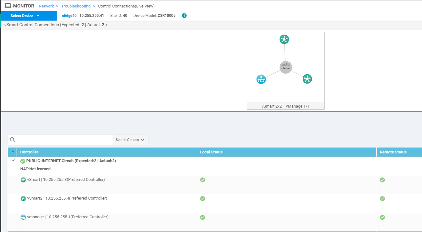
Click on cEdge40 and go to Troubleshooting. Select Control Connections (Live View) and we should see the cEdge has established control connections with vManage and the vSmarts
-
Navigate to Dashboards => Main Dashboard and we will see 4 Sites with Full WAN connectivity and 8 WAN Edges (or 6 WAN Edges, depending on the scenario chosen while requesting for these labs)
-
Log in to the CLI of cEdge40 via Putty
-
Issue
show sdwan control connectionsand we should see connections to the vSmarts and the vManage (same information that we saw on the GUI)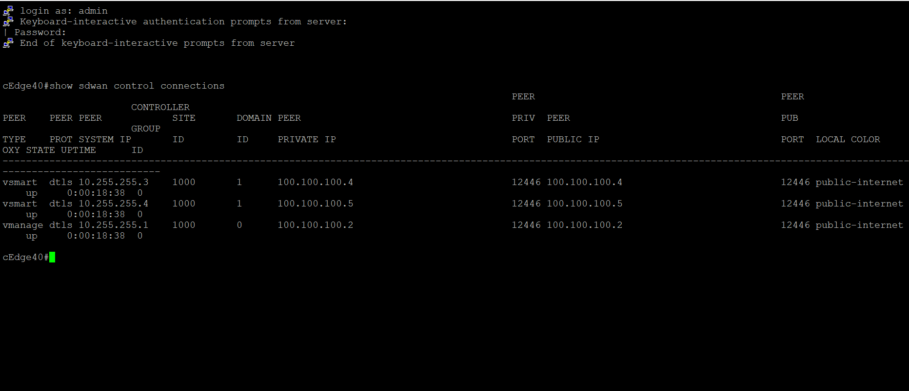
show sdwan control connectionsTip: Injectsdwanin show commands that would normally be used on vEdges and they should work on cEdges -
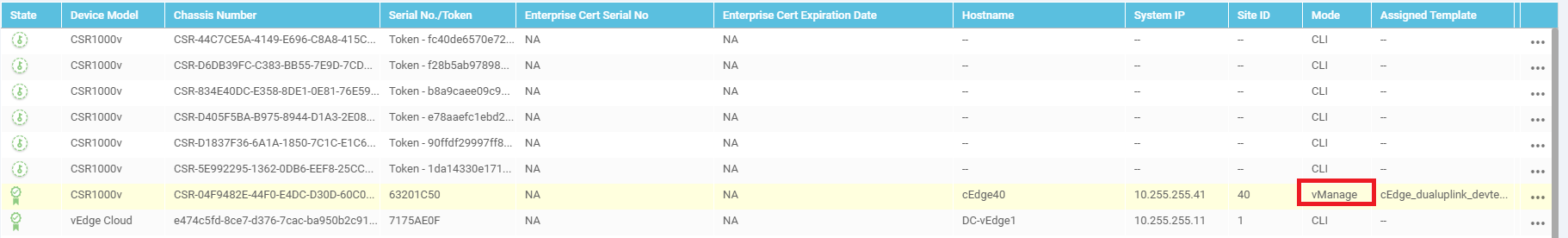
On Configuration => Devices in the vManage GUI, you will notice that the cEdge is in vManage mode. This is because we have attached a Device Template to it. Changes to the cEdge can only be made from vManage now. We will be converting the rest of the devices (which are in CLI mode right now) to vManage mode over the course of the next few sections
-
Issue
show sdwan control local-propertieson the CLI of cEdge40. Notice that the root-ca-chain-status is Installed and the certificate is installed and valid. The chassis-num is the same as what was referenced on vManage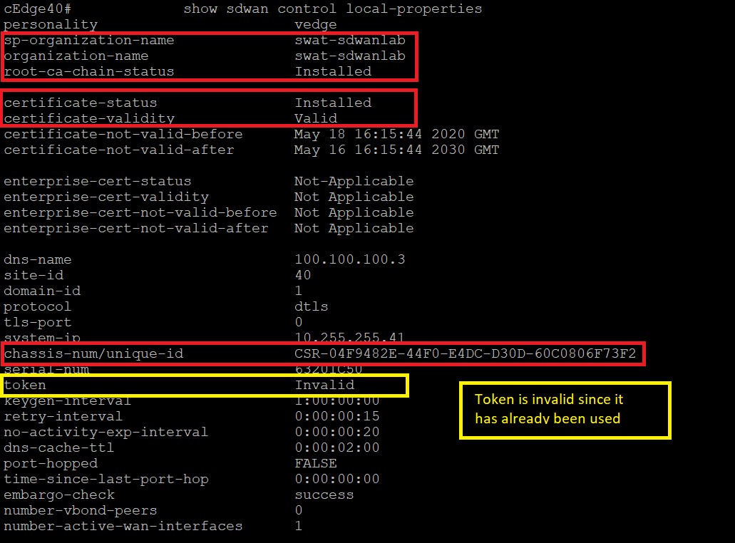
-
We can also use
show sdwan certificate installedto view the status of the installed certificates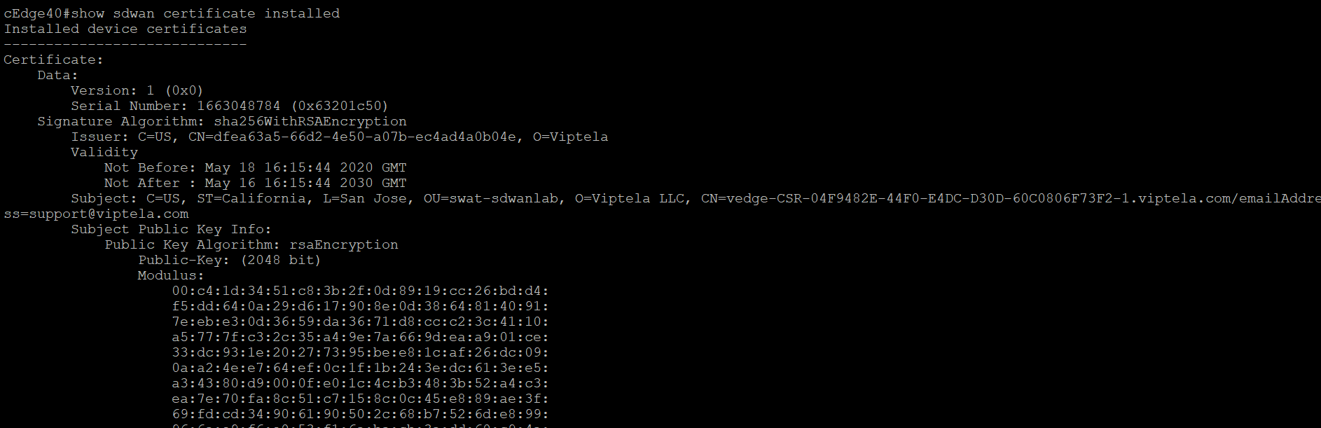
-
To view the SDWAN specific running configuration on a cEdge device (other than the well known
show running-config) useshow sdwan running-config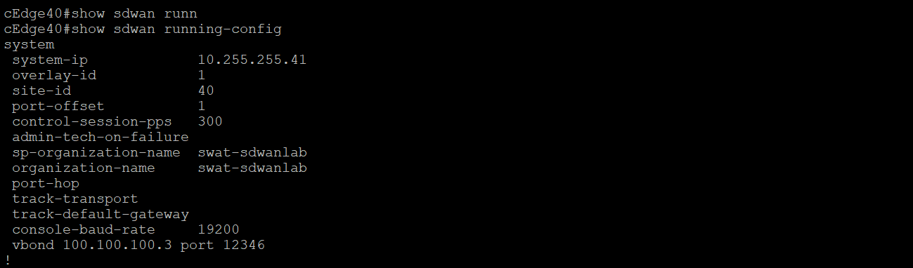
We have completed onboarding verification