- Overview
- Creating and Activating the AAR Policy
- Viewing modified traffic flows and current network statistics
- Configuring a Policer to simulate network impairment
- Creating a Policer List
- Configuring the IPv4 ACL Policy
- Applying the Policer on the MPLS link
- Viewing changed statistics and resultant traffic flows
Overview
While we can use Traffic Engineering to steer traffic towards a particular preferred transport, Application Aware Routing takes things to a different level by not only allowing us to punt traffic over a preferred path, but also define SLA parameters for traffic to be redirected if network conditions aren’t favourable for the type of traffic.
To set a baseline, we will first see how traffic flows on VPN 10 (let’s assume that this VPN has Voice traffic in it). We will then implement AAR and SLA Classes to route traffic out a preferred transport and switch the chosen transport if SLA parameters are not met.
To check existing traffic flows, follow the steps below:
-
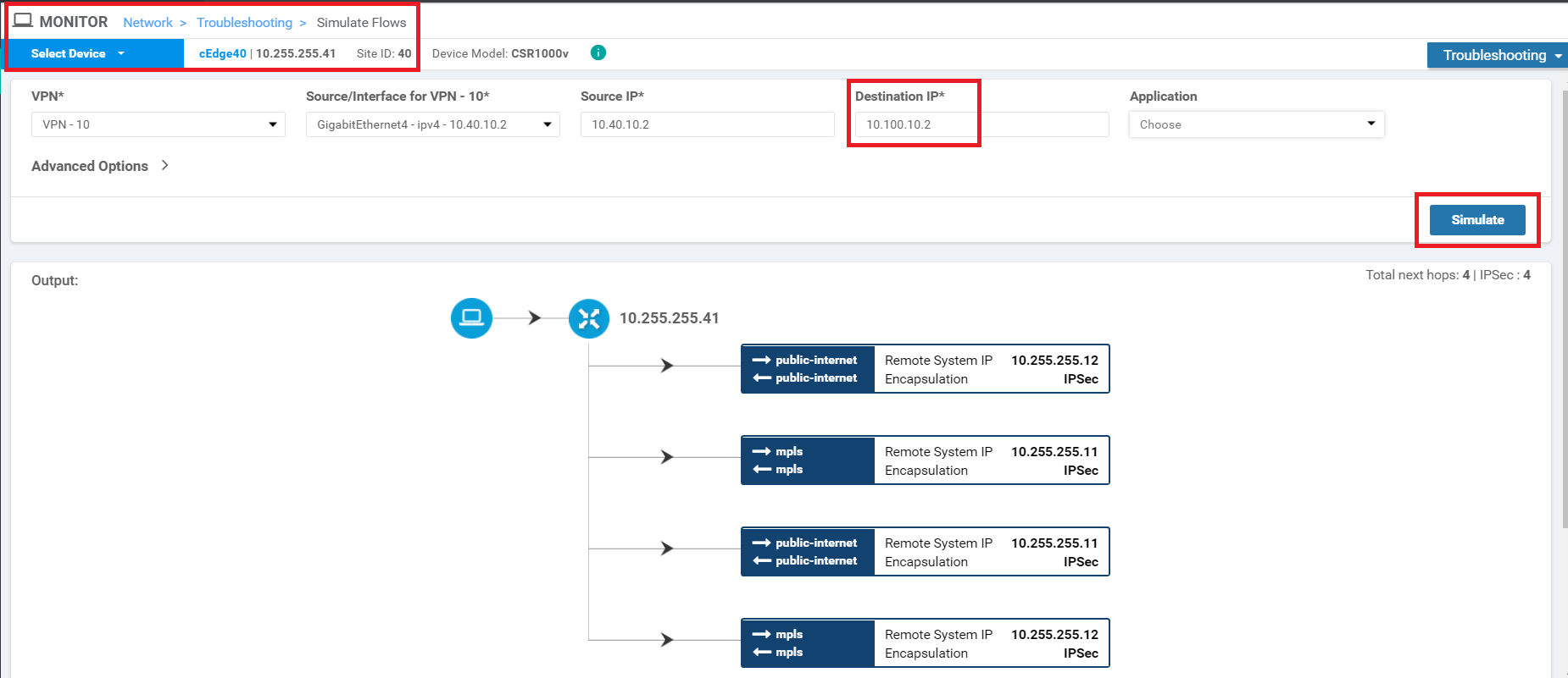
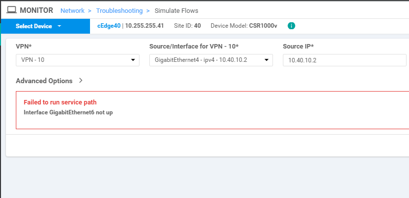
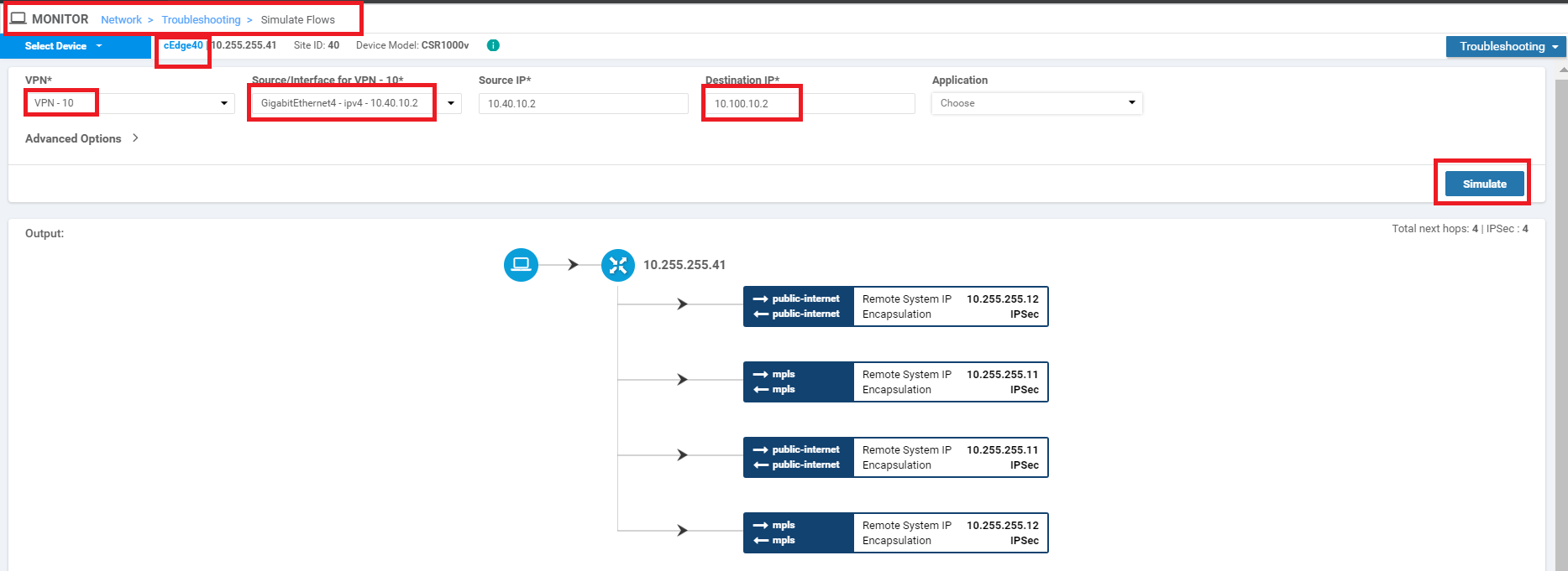
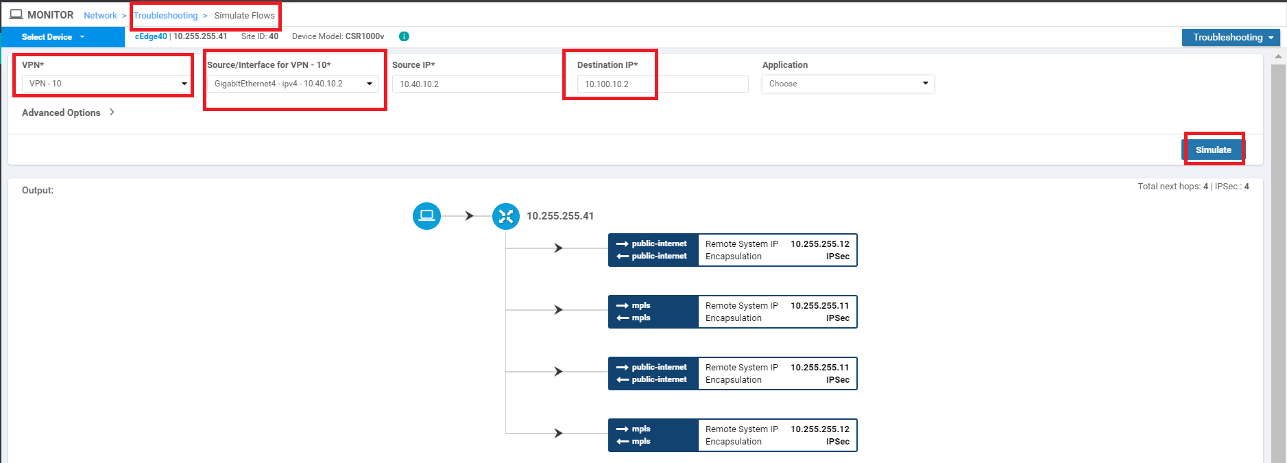
Navigate to Monitor => Network and select cEdge40 from the list. Scroll down on the left-hand side and click on Troubleshooting. Choose Simulate Flows. Choose a VPN of VPN - 10 and a Source/Interface of GigabitEthernet4. Enter the Destination IP as 10.100.10.2 and click on Simulate. Notice that traffic is attempting to use all available transports. If you receive an error of "Failed to run service path" as shown in the second image below, log in to vCenter and right click on the cEdge40 VM for your POD. Choose Edit Settings and uncheck the "Connected" check box for Network Adapter 4. Click on OK. Wait for 10 seconds and check the same checkbox again. Now try to simulate the flow
-
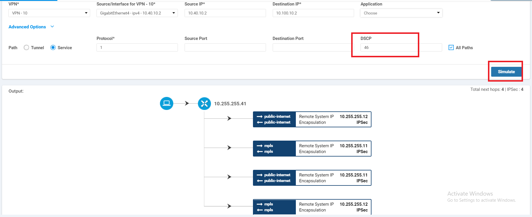
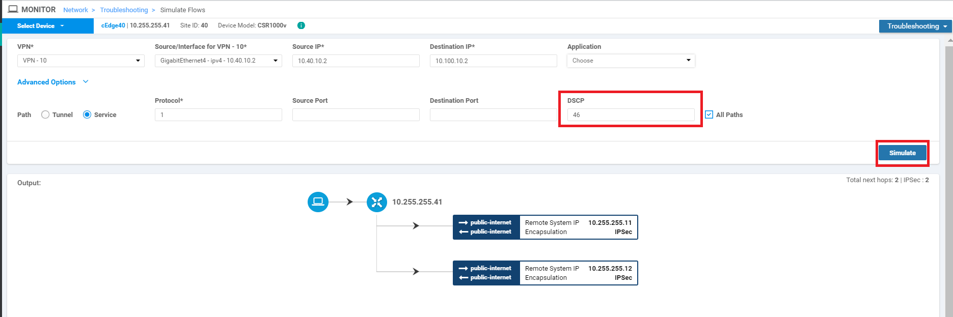
Click on Advanced Options and enter the DSCP value as 46 (i.e. VoIP RTP traffic). Click on Simulate. This traffic also uses all possible transports, which might not be ideal for our network
-
- Creating and Activating the AAR Policy
- Viewing modified traffic flows and current network statistics
- Configuring a Policer to simulate network impairment
- Creating a Policer List
- Configuring the IPv4 ACL Policy
- Applying the Policer on the MPLS link
- Viewing changed statistics and resultant traffic flows
Creating and Activating the AAR Policy
We will now set up an AAR Policy for VoIP (i.e. DSCP 46) traffic.
-
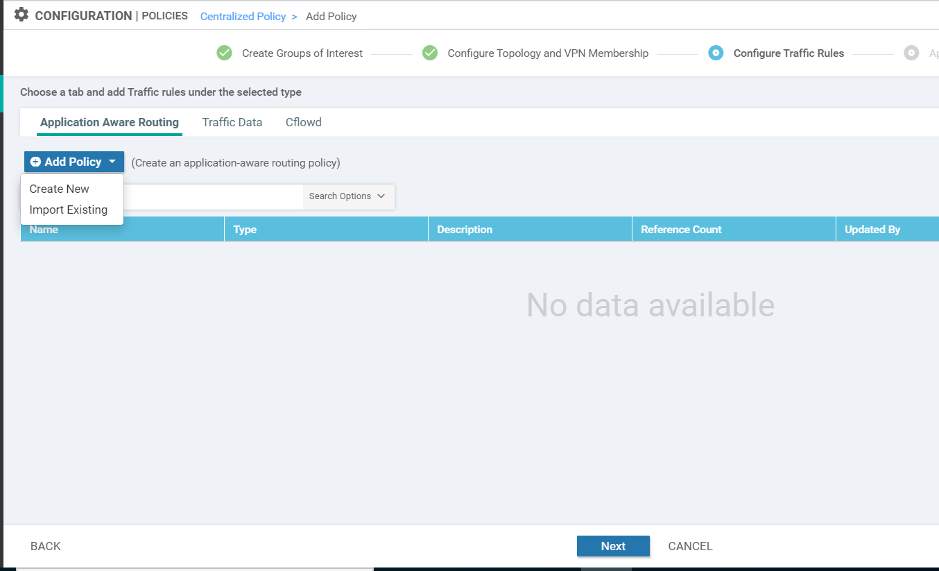
On the vManage GUI, go to Configuration => Policies and click Add Policy. Click on Next twice (till you get to the Configure Traffic Rules page) and click on Add Policy under Application Aware Routing. We thus have an overarching Policy (let’s call it the Main Policy) and an application-aware routing policy within it. As of now, we will configure the AAR routing policy. Towards the end, we will enter the details of the Main Policy
-
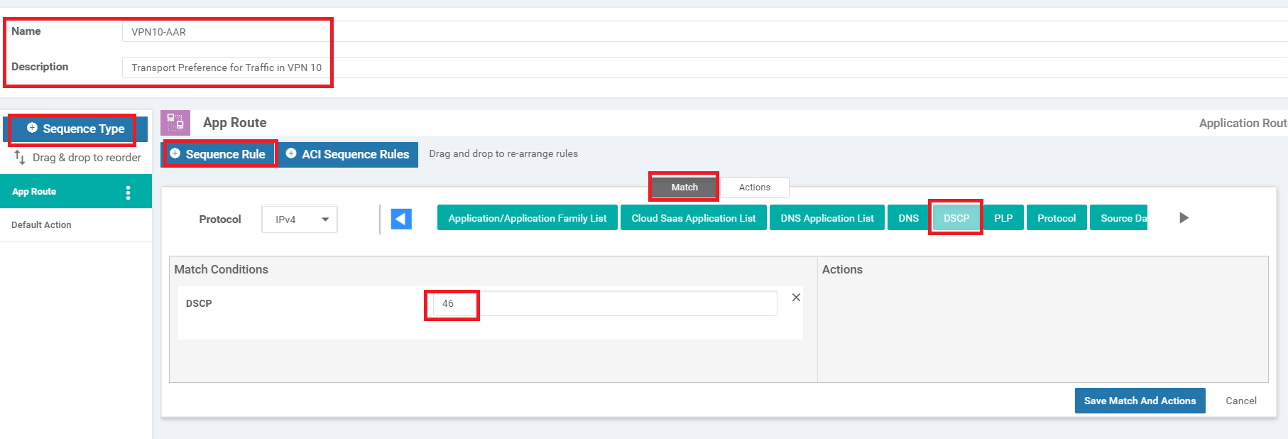
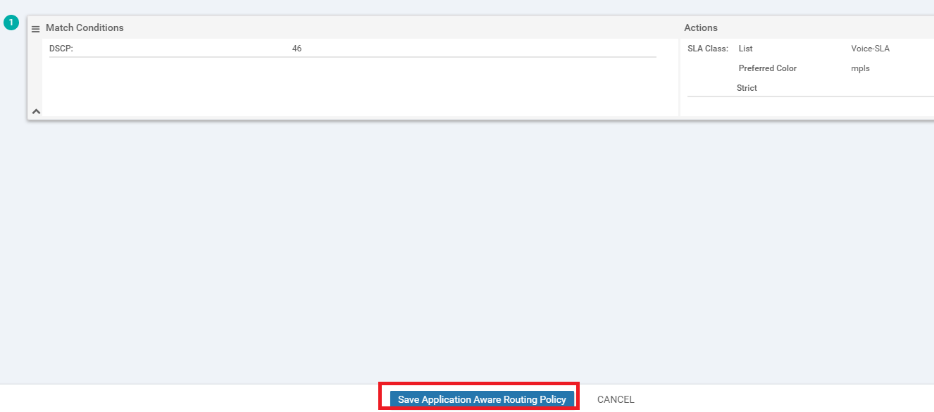
Give this AAR Policy a name of VPN10-AAR and a Description of Transport Preference for Traffic in VPN 10. Click on Sequence Type and then click on Sequence Rule. Under Match, select DSCP and enter a DSCP value of 46 under Match Conditions
-
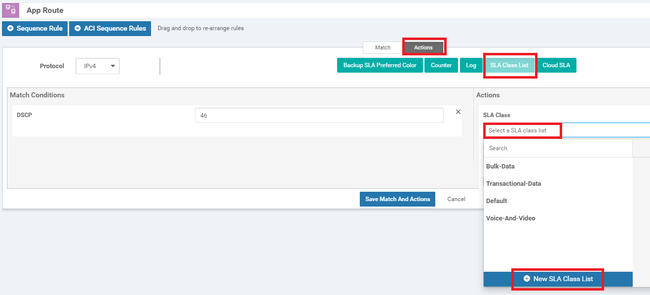
Click on the Actions tab and choose SLA Class List. Click on the box under SLA Class and choose New SLA Class List
-
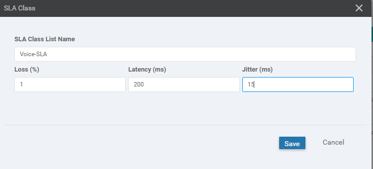
Give the SLA Class a Name of Voice-SLA and specify the Loss % as 1. Enter 200 for the Latency and 15 for the Jitter. Click on Save
-
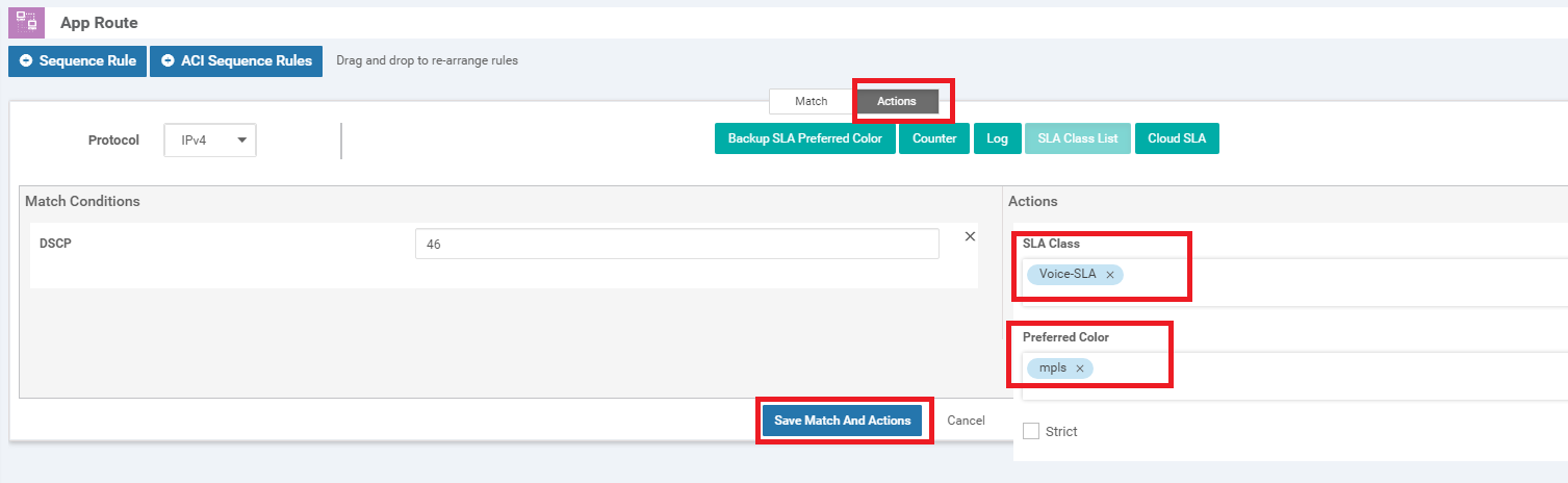
Still under actions, select the Voice-SLA SLA Class that we just created and set the Preferred Color to mpls. Click on Save Match and Actions
-
Ensure your App Route looks like the image below and click on Save Application Aware Routing Policy. Click Next
-
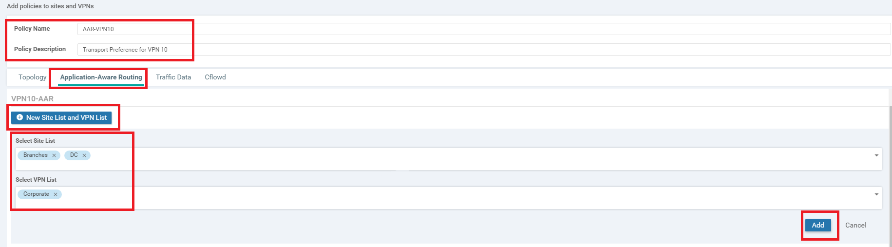
At the Apply Policies to Sites and VPNs page, give the Policy a Name of AAR-VPN10 and a Description of Transport Preference for VPN 10. Click on the Application Aware Routing tab and click on New Site List and VPN List. Under Select Site List choose Branches and DC. Under Select VPN List choose Corporate. Click on Add
-
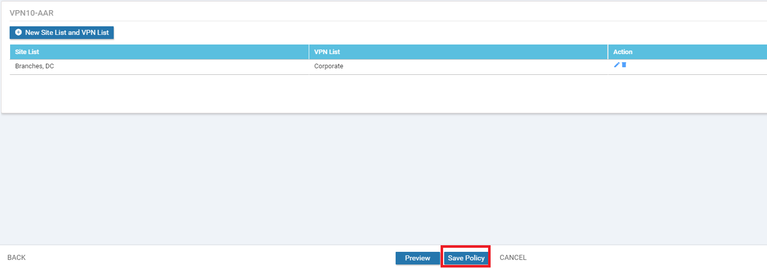
Click on Save Policy in the lower middle part of the screen to save our AAR Policy
-
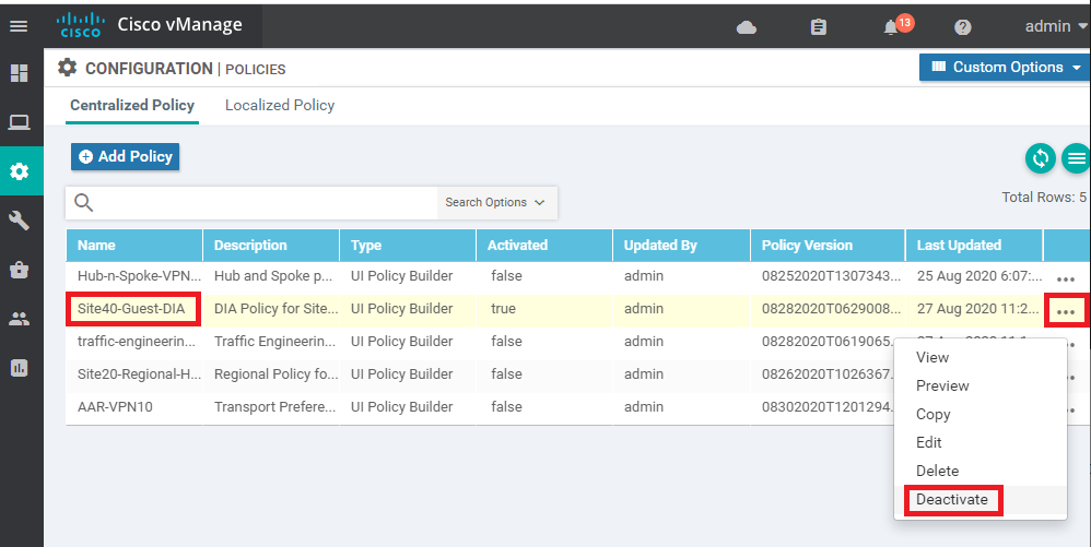
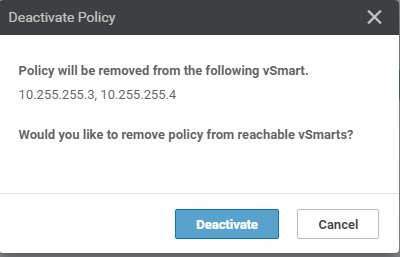
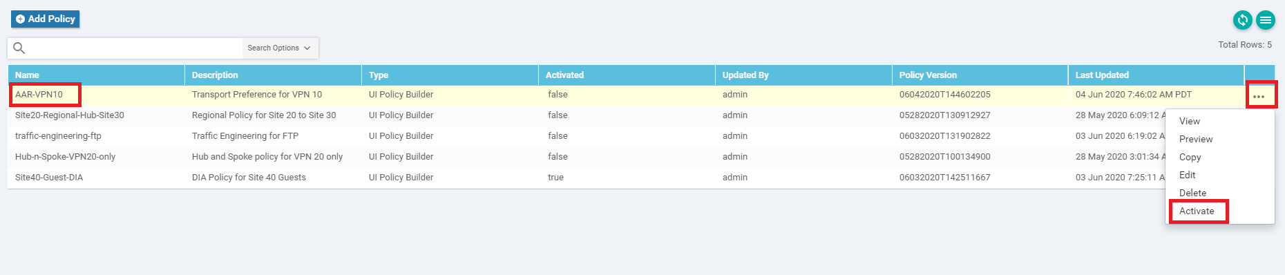
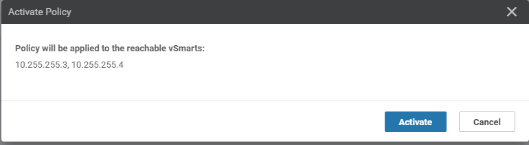
Click on the three dots next to the Site40-Guest-DIA policy created before (if some other policy is active, identify that policy) and choose to Deactivate it (this needs to be done due to a bug present in version 20.3.x of vManage, else Activation of the AAR policy we just created will give an error of a "bad-element" in the configuration). Confirm the Deactivation. Once done, click on the three dots next to the AAR-VPN10 policy we just created and choose to Activate it. Click on Activate again
-
-
- Viewing modified traffic flows and current network statistics
- Configuring a Policer to simulate network impairment
- Creating a Policer List
- Configuring the IPv4 ACL Policy
- Applying the Policer on the MPLS link
- Viewing changed statistics and resultant traffic flows
Viewing modified traffic flows and current network statistics
To view the changes made by the Policy on our network, follow the steps below.
-
On the vManage GUI, go to Monitor => Network and click on cEdge40. Choose Troubleshooting from the left-hand column and click on Simulate Flows. Enter the VPN as VPN - 10 and the Source/Interface as GigabitEthernet4. Set a Destination IP of 10.100.10.2 and click on Simulate. We find that traffic is taking all possible transports, just like before. This is expected since we haven’t defined anything for regular traffic
-
On the same screen, click on Advanced Options and set the DSCP to 46. Click on Simulate
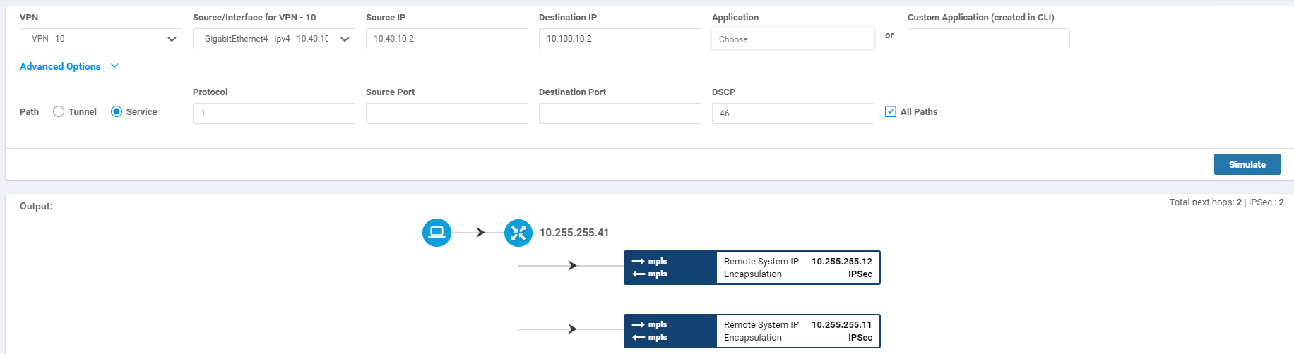
VoIP Traffic is now traversing the MPLS link as the preferred route.
-
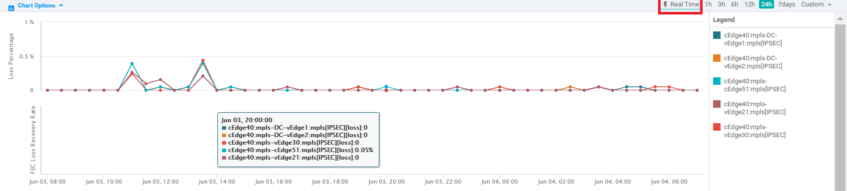
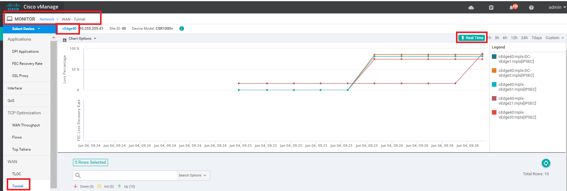
We will now check the current network statistics. Go to Monitor => Network => cEdge40 => Tunnel and put a check mark against all the mpls Tunnel Endpoints. Click on Real-Time after scrolling up to the chart and make sure Packet Loss/Latency is checked under Chart Options. We may see negligible packet loss occurring (let the chart run for 5 minutes before analysing, it should get updated every few seconds)
-
-
-
- Configuring a Policer to simulate network impairment
- Creating a Policer List
- Configuring the IPv4 ACL Policy
- Applying the Policer on the MPLS link
- Viewing changed statistics and resultant traffic flows
Configuring a Policer to simulate network impairment
In order to simulate impairment in the network (Packet Loss and Latency), we can use a Policer and a Shaper. Over here, we will configure a Policer which will be applied to the MPLS link in order to simulate Packet Loss.
Later on, we will leverage a Shaper to simulate Latency.
Creating a Policer List
-
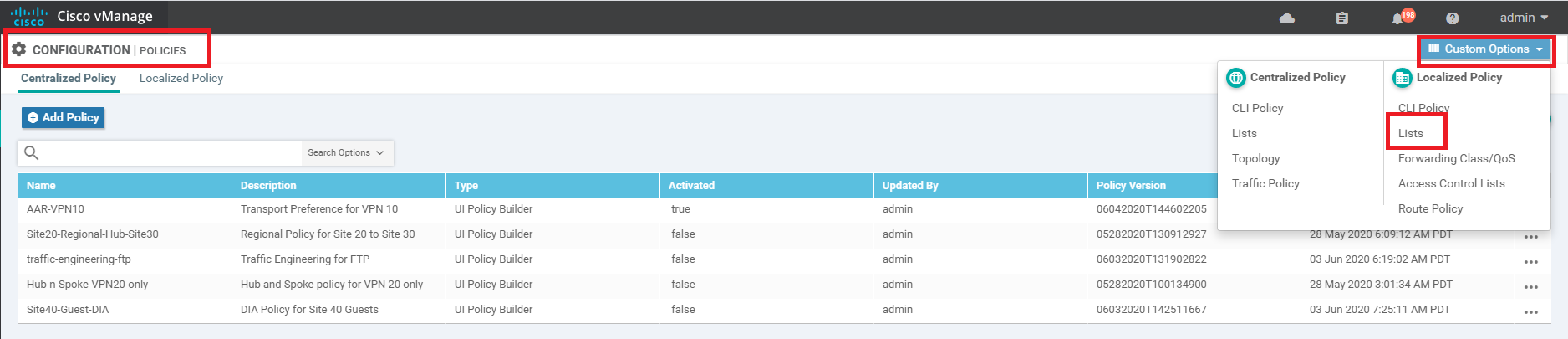
On the vManage GUI, navigate to Configuration => Policies. Click on Custom Options (top right-hand corner). Under Localized Policy click on Lists
-
Click on Policer (left-hand side) to create Policer configuration which will simulate network impairment on our MPLS link (Packet Loss). Click on New Policer List and give it a name of AAR-Impair-Policer-PL. Specify the Burst as 15000 and Exceed as Drop. The Rate should be 7000. Click on Add
Field Value Policer List Name AAR-Impair-Policer-PL Burst (bps) 15000 Exceed Drop Rate (bps) 7000 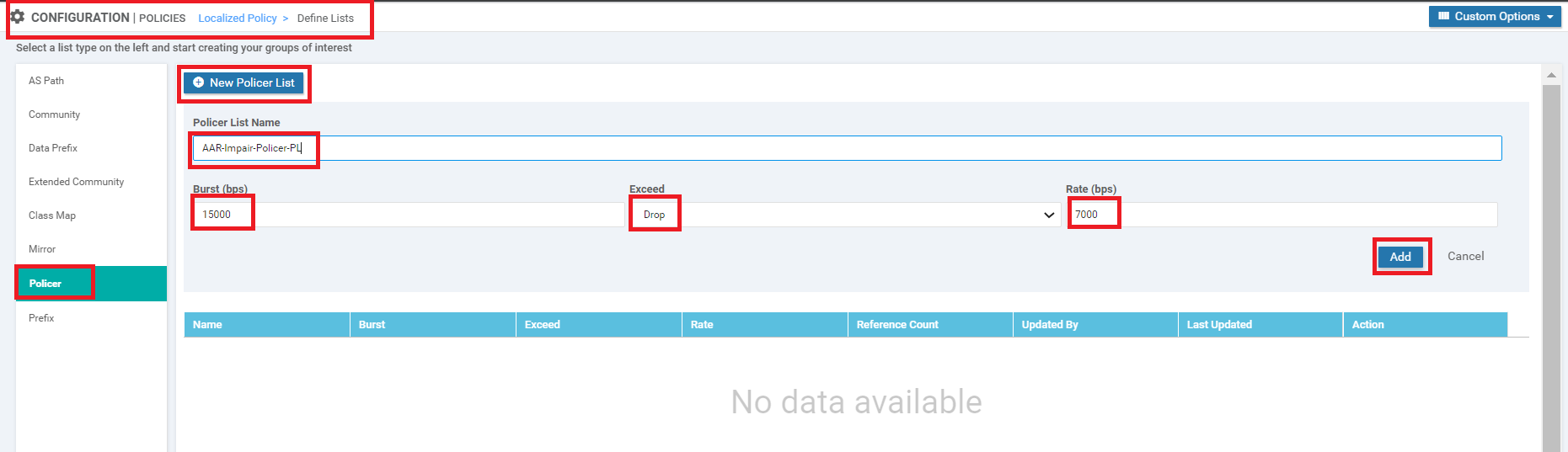
-
-
-
- Configuring a Policer to simulate network impairment
-
- Configuring the IPv4 ACL Policy
- Applying the Policer on the MPLS link
- Viewing changed statistics and resultant traffic flows
Configuring the IPv4 ACL Policy
-
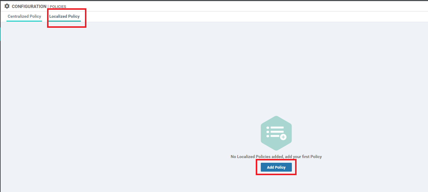
Go to the Localized Policy tab and click on Add Policy
-
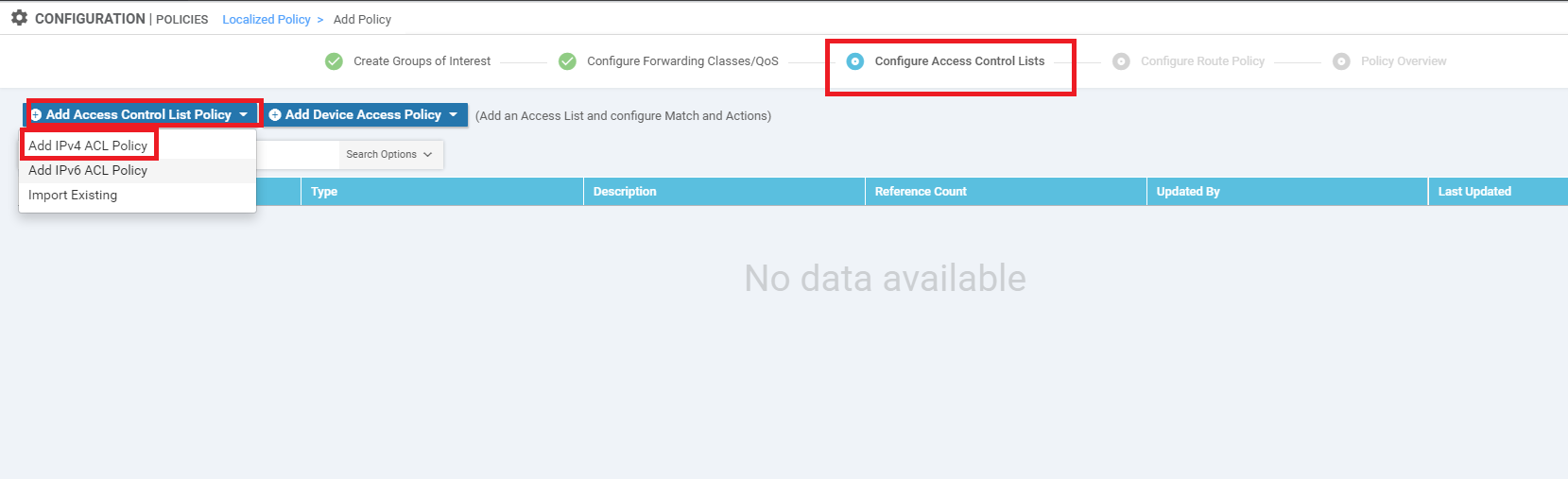
Click Next till you are at the Configure Access Control Lists page. Click on Add Access Control List Policy and choose Add IPv4 ACL Policy
-
Enter a name of Impair-PL-AAR with a Description of Impairment ACL. Click on Add ACL Sequence and click on Sequence Rule. Go to the Actions tab and make sure the Accept radio button is selected. Choose Policer and select the AAR-Impair-Policer-PL we created before. Click on Save Match and Actions. Refer to the table and image below
Step Field Value 1 Name Impair-PL-AAR Description Impairment ACL 2 Add ACL Sequence 3 Sequence Rule 4 Actions 5 Policer 6 Policer AAR-Impair-Policer-PL 7 Save Match and Actions 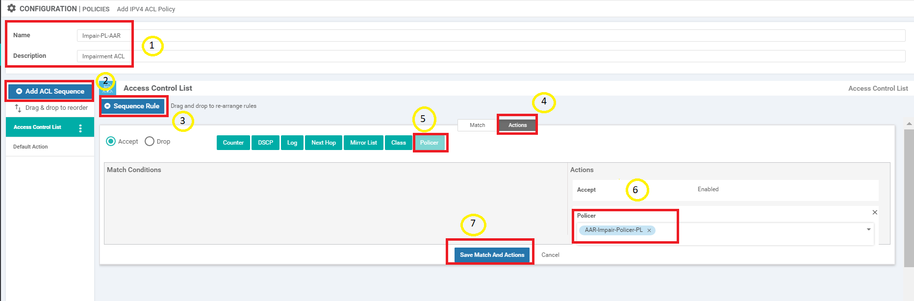
-
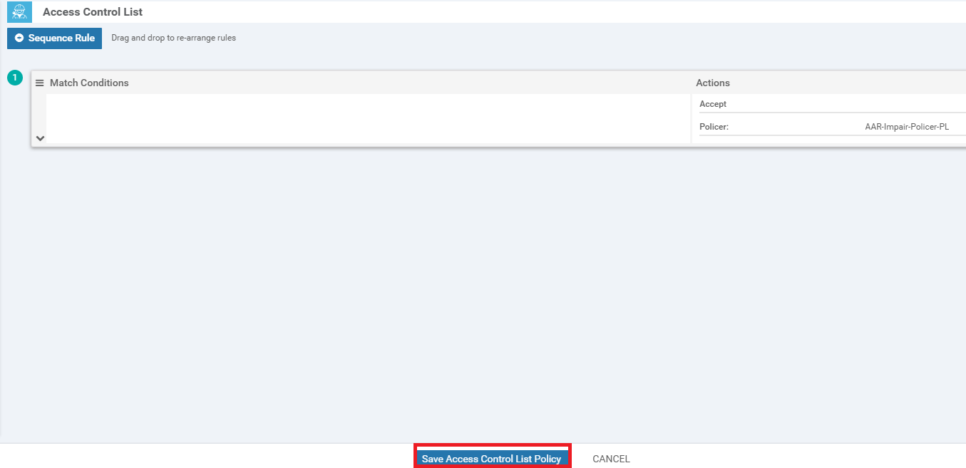
Click on Save Access Control List Policy
-
On the Policy Overview page (this is our Main Policy), enter a Policy Name of Policer-AAR-Impairment and a Description of Injecting Impairment for AAR via a Policer - Packet Loss. Click on Save Policy
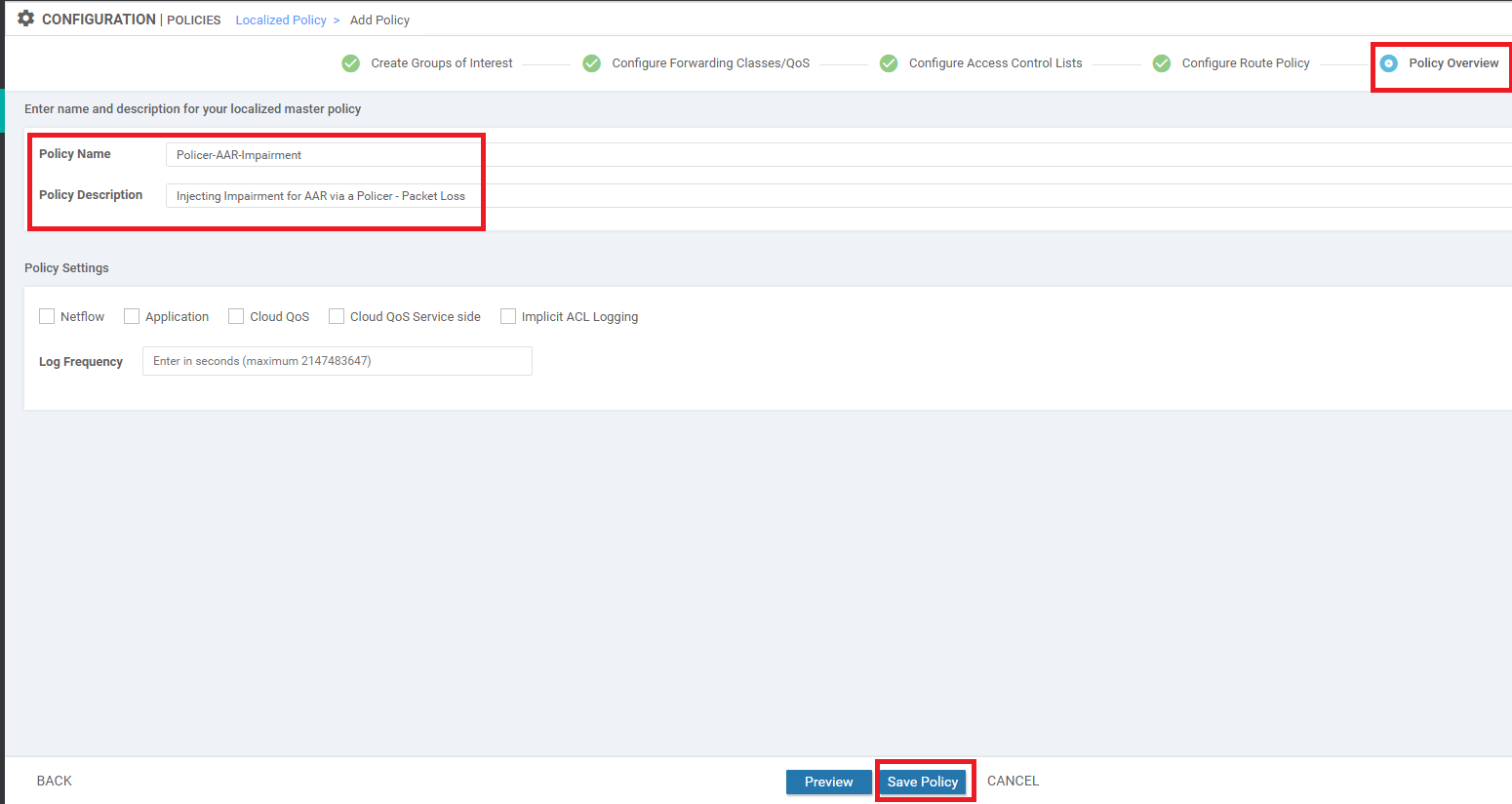
We have completed configuration of our Policer. It needs to be applied to a link in order to simulate network impairment.
-
-
-
-
-
-
- Applying the Policer on the MPLS link
- Viewing changed statistics and resultant traffic flows
Applying the Policer on the MPLS link
-
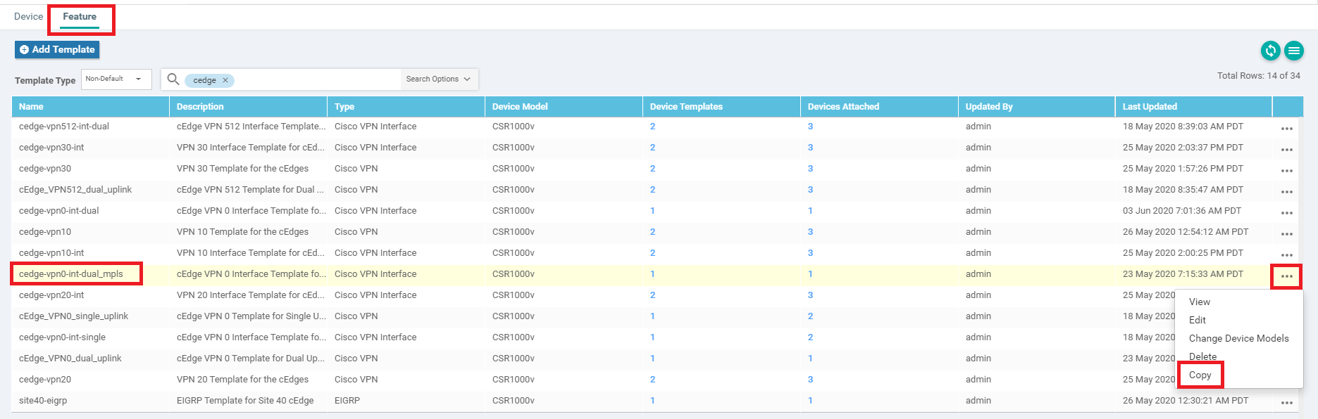
Navigate to Configuration => Templates => Feature Tab and locate the cedge-vpn0-int-dual_mpls VPN Interface template. Click on the 3 dots next to it and choose to Copy
-
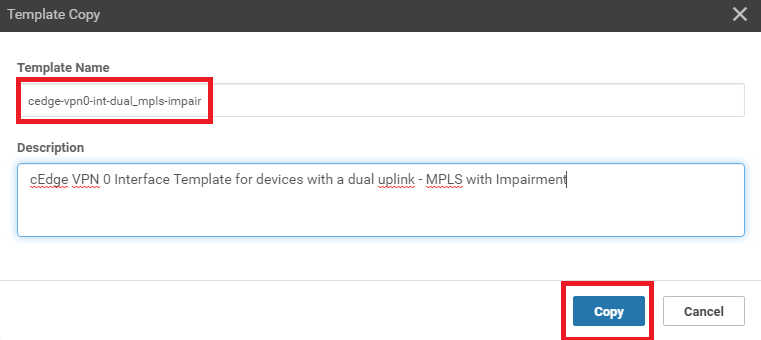
Rename it t0 cedge-vpn0-int-dual_mpls-impair and a Description cEdge VPN 0 Interface Template for Devices with a dual uplink - MPLS with Impairment. Click on Copy
-
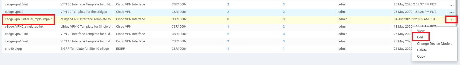
Click on the three dots next to this newly copied template and click on Edit
-
Navigate to the ACL/QoS section and modify the following fields. Click on Update
Field Global or Device Specific (drop down) Value Ingress ACL - IPv4 Global On IPv4 Ingress Access List Global Impair-PL-AAR Egress ACL - IPv4 Global On IPv4 Egress Access List Global Impair-PL-AAR 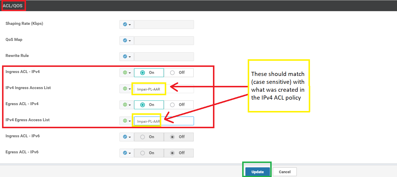
-
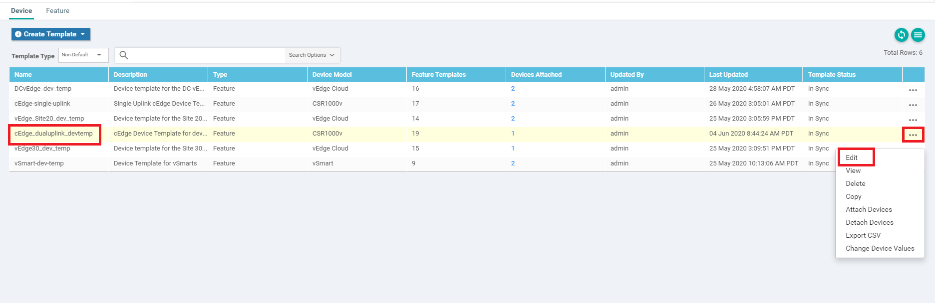
Under Configuration => Templates go to the Device tab and locate the cedge_dualuplink_devtemp template. Click on the three dots next to it and choose to Edit
-
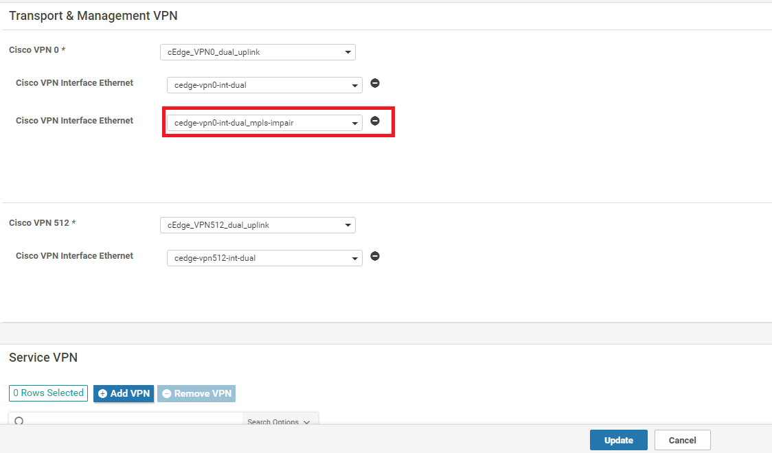
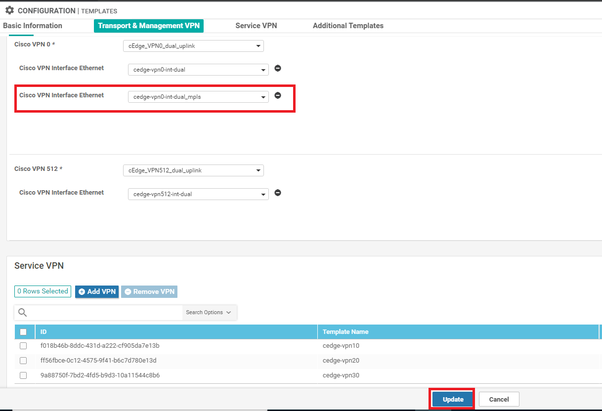
Under Transport & Management VPN, update the Cisco VPN Interface Ethernet from cedge-vpn0-int-dual_mpls to cedge-vpn0-int-dual_mpls-impair. Make sure this is done on the VPN interface for the MPLS link
-
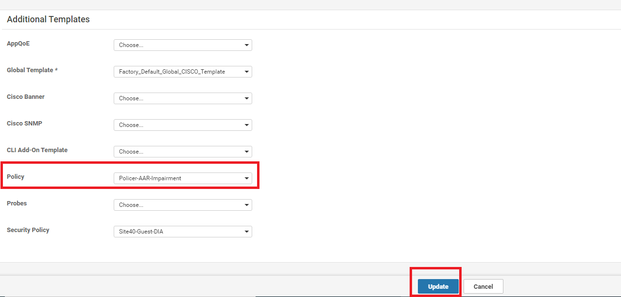
Scroll down to the Additional Templates section and update the Policy to Policer-AAR-Impairment. Click on Update. Click on Next
-
You can choose to view the Side by Side or simply click on Configure Devices
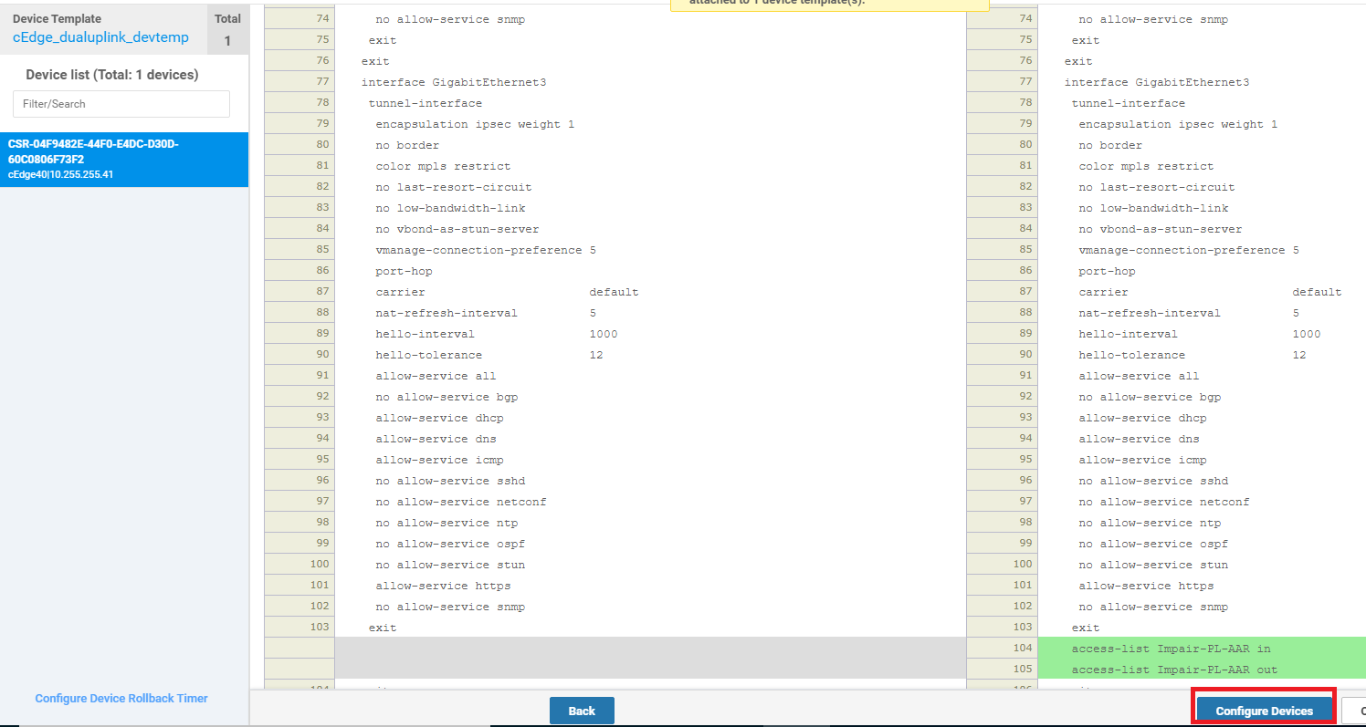
This completes the implementation of our Policer on the MPLS link to simulate network impairment.
-
-
-
-
-
-
-
- Viewing changed statistics and resultant traffic flows
Viewing changed statistics and resultant traffic flows
-
Navigate to Monitor => Network and click on cEdge40. Click on Tunnel on the left-hand side and make sure all the MPLS Tunnel Endpoint entries are selected, with the public-internet entries being unchecked. Click on Real Time (top right corner) and the Chart Options drop-down (top left corner) is set to Loss Percentage/FEC Loss Recovery Rate. Let this run for a few minutes - you will notice a spike in Packet Loss
-
Head over to Troubleshooting (left-hand side, might need to scroll down) and click on Simulate Flows. Enter the VPN as VPN - 10, the Source/Interface as GigabitEthernet4 and the Destination IP as 10.100.10.2. Click on Simulate. There should be no change in traffic flow for General traffic, which will still use all available transports
-
Under Advanced Options, set DSCP to a value of 46 and click on Simulate. You will notice that VoIP traffic (i.e. DSCP 46) is now taking the Internet path since MPLS doesn’t conform to the SLA requirements that we defined. Compare the current traffic flow with the one in Step 2 over here
-
We will now revert the configuration to what it was pre-impairment. Go to Configuration => Templates and locate the cEdge_dualuplink_devtemp. Click on the three dots next to it and Edit. Change the Cisco VPN Interface Ethernet value under Transport & Management VPN back to cedge-vpn0-int-dual_mpls and click on Update. Click on Next and Configure Devices
-
Wait for approximately 3 minutes and head over to Monitor => Network => cEdge40 => Troubleshooting => Traffic Flows. Enter the same details as in Step 3 above and click on Simulate. VoIP traffic should traverse over the MPLS link again
This completes the Application Aware Routing section of the lab.
-
-
-
-
-
-
-
-